


11
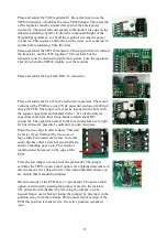
Place and solder the 7805 regulator IC. Be careful not to use the
TIP122 transistor, which has the same TO220 shape! The metal tab
of the regulator must be oriented away from the black power
connector. The metal tab corresponds to the thick wide edge on the
silkscreen drawing. I prefer to limit the component height of the
Wisp648 programmer, so I bend the regulator towards the power
connector. This requires a little slack in the wires, so it is easiest to
do this before soldering. Trim the wires.
Place and solder the TIP122 transistor. Check again that it is indeed
the transistor, not the 7805 regulator! The metal tab of the
transistor must be oriented towards the resistors. Like the regulator,
I prefer to bent the TIP122 slightly over the resistors.
Place and solder the big black RJ11/12 connector.
Place and solder the two 470
µ
F electrolytic capacitors. The recent
versions of the PCB have one 470
µ
F capacitor and one of 2200
µ
F,
check the PCB. The longer wire must be inserted in the hole with
the square copper pad and marked with a +. Or: all electrolytic
capacitors must have their white bands towards the DB15
connector. The capacitor nearest to the four diodes has a very tight
fit, but with some pressure I could always push it in place,
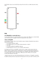
Place the two chips in their sockets. This will
be easier if you first bent the two rows of
legs a little bit towards each other. Note that
each chip has either a notch at one small side,
and/or a marking near a pin. This notch or
marking must be nearest to the edge of the
PCB.
Place the pin jumper on one pin of the pin header. The jumper
activates the TIP122 power-short option. As explained elsewhere in
this document, it is advised to have this option disabled unless you
are certain that it should be enabled.
Recent versions of the PCB have a 3-pin header. The power-short
option is activated by placing the jumper nearest to the resistors.
The power-short is disabled by removing the jumper, or (at a
request from a user who kept losing the jumper) by placing it in the
position away from the resistors. On the most recent version of the
PCB this position is marked ‘dis’, the active position is marked
‘ena’.