


P/N: 4MB020-010
©2003 Vortech Engineering, LLC
All Rights Reserved, Intl. Copr. Secured
06DEC02 V1.0(4MB HP500 v1.0)
10
6. FUEL SYSTEM UPGRADE
A. Disconnect the fuel lines connecting to the
mechanical fuel pump.
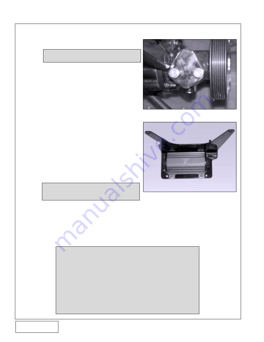
B. Remove the mechanical fuel pump and plug the
vacuum port on the manifold that has a vacuum
line running to it. Use the provided fuel pump
block-off plate and gasket along with the stock
hardware to cover the exposed area. (See
Fig.6-a .)
C. Disconnect the fuel lines from the fuel water
separator and remove the fuel/water separator
mount and filter.
D. Disconnect and remove all fuel lines.
E. Remove the cool fuel pump assembly located
below the crank pulley and both water lines
connecting to it.
F. Remove the cool fuel bracket assembly from the
bracket.
G. Mock up the new fuel pump and filter on the
bracket to check for clearance.
H. Using the new fuel pump as a guide, center the
fuel pump (see Fig. 6-b) on the bracket and mark
the four holes onto the bracket. Using a letter "K"
(Ø.281") drill bit and drill motor, drill out the
previously marked holes. Secure the fuel pump
to the bracket using the four 1/4-20 x 1" SHCS,
1/4" washers and nylock nuts.
I.
Supplied in this kit is ten feet of #8 and eight feet
of #6 fuel line, 5 #8 and 4 #6 female swivel
fittings. Measure the distances between each of
the fuel system components and write the lengths
next to each fuel line on the diagram. It is impor-
tant to maintain a fuel line routing that is not near
moving parts, having excessive length or unusu-
ally tight bends that will inhibit the proper opera-
tion of the fuel system.
Fig. 6-b
NOTE:
The inlet of the fuel pump should point to-
ward the starboard side when mounted.
NOTE:
Cut all hoses square with a fine tooth hacksaw or abrasive cut-off wheel.
Lubricate the nipple of the female swivels with oil to aid installation and
all O-rings to avoid pinching of chafing. Clean all fuel lines prior to
installation as any debris in the fuel line may cause complete or partial
fuel system failure. Hose assemblies should be tested hydrostatically at
twice the recommended working pressure of the hose (150 psig). All
fuel system components must be completely and properly installed
into hoses or death may occur. Route each fuel line per Fig.5-c. As-
semble the ends with their associated fuel system hardware fittings.
When routing fuel lines be sure not to kink or have any tight bends in
the lines. Keep lines away from any moving parts or hot surfaces. Use a
small amount of clean engine oil to lubricate all of the O-rings in the
fuel system prior to installation.
Fig. 6-a
NOTE:
Some engine systems do not have a me-
chanical fuel pump.


