


VOCOM II
Operation Instructions
The information is developed by
©
Volvo Group in Sweden.
69
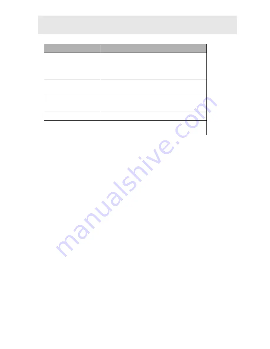
Parameter
Description
WLAN interface
IEEE 802.11 a/b/g/n
Dual band support 2.4/5-GHz
MIMO support, 2 WLAN antennas
(WiFi-Direct support)
Diagnostic APIs
RP1210C, J2534, J2534-1, VOCOM II Smartphone
API
Processing
Connectivity CPU
Qualcomm/Atheros AR9350 SoC
Vehicle CPU
SmartFusion2 SoC
Memory
2 x 128-MB DDR RAM, 128 MB NAND FLASH, 16 MB
NOR FLASH
Tab. 11
–1: Technical specifications of VOCOM II


