P 120
REPAIR INSTRUCTIONS
FRONT END
Front mudguards
The front mudguard is removed by taking out the
following screws: the screw between the mudguard
and stay at the lower side member, the screw bet-
ween the mudguard and body side behind the
above-mentioned stay, the screws in the front side
section and the screws in the upper side member.
I n addition, the headlamp with leads must be re-
moved. Concerning removing the headlamp, see
Part 3. Fitting is done in the reverse order.
Front section
The front section is attached to the front mudguards,
wheel arch plates and the upper and lower cross-
members.
When removing, take out the headlamps, the screws
between the front section and splash guard under
the headlamp, the screws in the upper and lower
cross-members and the screws in the wheel arch
plates.
Bonnet and bonnet lock
The bonnet is attached by means of screws in each
hinge. The bonnet is removed by taking out the
screws between the hinges and bonnet. The hinges
are attached to the body with four screws each.
All the holes in the hinges are oval in order to
permit the bonnet to be adjusted.
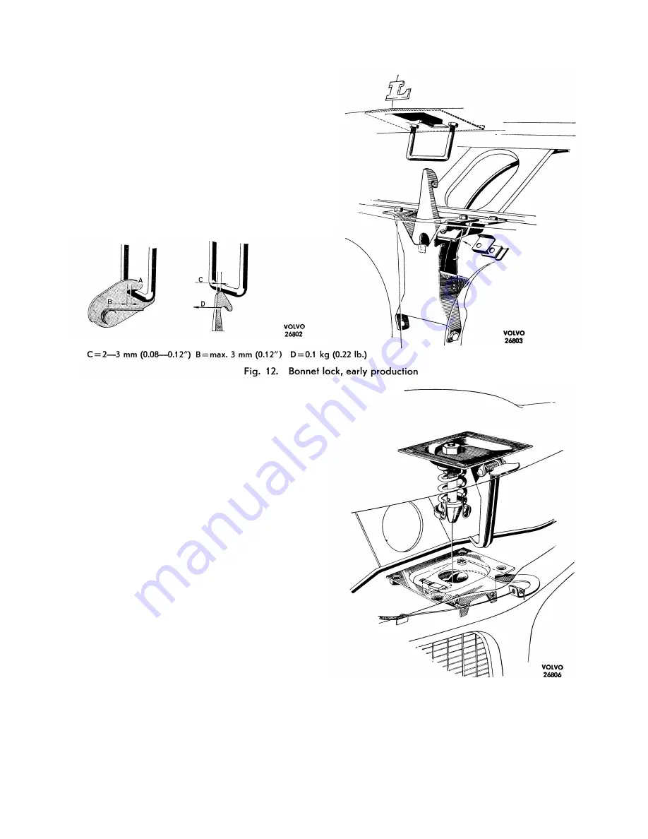
There are two types of bonnet lock. The early pro-
duction lock (up to chassis number about 10 000)
is illustrated in Fig. 12. The bonnet lock is adjusted
as follows.
When the bonnet is locked the U-shaped catch
should lie right inside the lock catch groove and
the measurement B, Fig. 12 must not exceed 3 mm
(0.12"). Any adjustment should be made on the
catch itself. It should be adjusted vertically so that
the gap between the bonnet and the front section
Fig. 13.
Bonnet lock, late production
of the body is 4.5 ± 1 mm (0.18 ± 0.04"). The tension
of the safety catch spring should be at least 0.1 kg
(0.22 lb.) measured at D, Fig. 12, in order to move
it from its rest position.
8--7


