Engine installation
64
Alignment
When the bed frame is finally in position, the propel-
ler shaft installed and other preparatory work com-
pleted, the engine and reverse gear can be installed.
Engines with a closed coupled reverse gear are
lifted into position together with their gears.
The first alignment of the engine can be made no
matter whether the boat is ashore or afloat. Before
final alignment is started, however, the boat should
have been afloat for some days so that the hull is
subjected to the loading it has in its final form.
Checking flanges
There are two ways of making the alignment:
Method 1
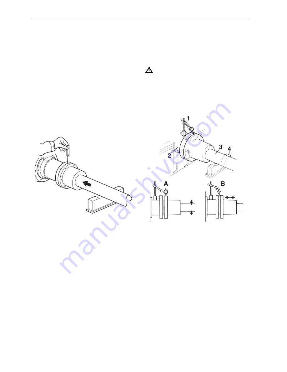
Checking parallel position of flanges
. Feeler gauge with thickness of 0. mm (0.004").
Check that the propeller shaft flanges are paral-
lel as shown in the figure above. Move the flanges
together so that the guides engage with each other.
Then check, with the flanges pressed against each
other, that they are parallel so that it is not possible to
insert an 0. mm (0.004") feeler gauge at any point
between the flanges. Then turn the flanges through
90°, 80° and 270° and repeat the check in the new
positions.
NOTE! Make sure that the flanges are pressed
against each other throughout the entire check.
When the engine is fitted on rubber mountings, align-
ment must be carried out with the same care as in
the case of fixed mountings.
IMPORTANT! The alignment should be re-
checked a few days after launch with the boat
completed and rigged (sailing yachts).
Method 2
This method is normally more accurate but requires
enough space to turn the dial indicator around fitted
to the reverse gear flange.
. Dial indicator with magnetic foot
2. Flange on reverse gear
3. Propeller shaft
4. Support
A. Checking radial deviation
B. Checking axial deviation (rocker gauge)
The flanges are checked using a dial indicator as
shown in the figure above.
The propeller shaft must then be pushed aft by about
0 mm (0.4") and well supported so that the shaft is
thoroughly centred. The shaft must also be fixed axi-
ally.
Turn the reverse gear flange and first measure the ra-
dial deviation as shown at A. Adjust the reverse gear
position, then measure the axial deviation according
to B with a rocker gauge against the flange contact
surface. The greatest permissible deviation in both
cases is 0. mm (0.004").
Summary of Contents for D11 series
Page 1: ...Marine Propulsion Diesel Engines Installation 1 1 D E D5 D16 series ...
Page 2: ......
Page 208: ...206 References to Service Bulletins Group No Date Concerns ...
Page 209: ...207 Notes ...
Page 210: ...208 Notes ...
Page 212: ...7748655 English 11 2007 ...


