Electrical system
40
Cable core area (mm
2
)
50
70
95
20
Cable core area
1)
(AWG)
/0
2/0
3/0
4/0
Engine
Electrical System
Total cable length m (ft)
D5/D7
2V
N/A
0–4.2
4.2–5.4
5.4–7.2
(0–3.8)
(3.8–7.6)
(7.6–23.6)
D5/D7
24V
0–3.0
3.0–7.8
7.8–23.0
23.0–3.0
(0–42.6)
(42.6–55.8)
(55.8–75.4)
(75.4–0.6)
D9
2V
0–5.0
5.0–8.0
8.0–0.0
0.0–3.0
(0–6.4)
(6.4–26.2)
(26.2–32.8)
(32.8–42.6)
D9/D
24V
N/A
0–8.0
8.0–0.0
0.0–3.0
(0–26.2)
(26.2–32.8)
(32.8–42.6)
D2
2)
24V
N/A
0–3.2
3.2–6.0
6.0–22.0
(0–42.8)
(42.8–52.4)
(52.4–72.2)
D6
24V
0–4.4
4.4–6.4
6.4–8.4
8.4–.0
(0–4.4)
(4.4–2.0)
(2.0–27.6)
(27.6–36.0)
1
) AWG (American Wire Gauge)
2
) Values based on battery capacity 40 Ah
Starting battery cable area
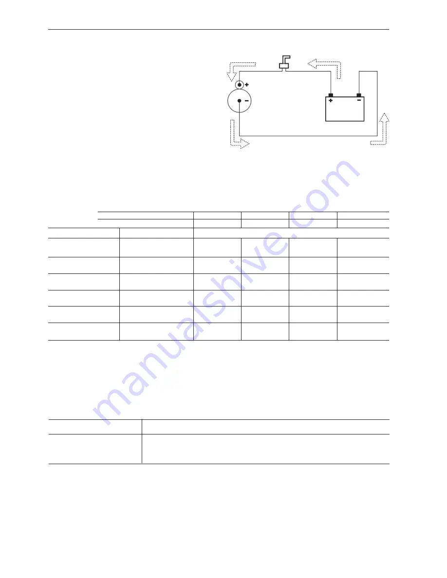
Volvo Penta recommends cable areas as below, to
provide sufficient power from the battery to the start-
er motor.
Measure the
total cable length from the battery
positive (+) terminal via the main switch to the starter
motor positive (+) terminal and from the starter motor
negative (–) terminal back to the battery negative (–)
terminal .
Thereafter select the recommended cable area ac-
cording to the table on the next page for
both the
negative (–) cable and the positve (+) cable.
Since the cable has to absorb generated heat, the
cross section area should not be less than 50 mm².
Keep the positive and negative wires to the starter
motor at approximately equal lengths and use the
same dimensions
Comparison cable core area (mm²) / diameter (mm) according to Volvo standard
Cable core area, mm²
50
70
95
120
Cable core diameter, mm
2
4
6
8
Cable diameter, mm
5
7
9
2
Starter
Battery
Main
switch
NOTE! If the vessel may operate in colder tempera-
ture than +5 °C, the cable size must be increased.
Summary of Contents for D11 series
Page 1: ...Marine Propulsion Diesel Engines Installation 1 1 D E D5 D16 series ...
Page 2: ......
Page 208: ...206 References to Service Bulletins Group No Date Concerns ...
Page 209: ...207 Notes ...
Page 210: ...208 Notes ...
Page 212: ...7748655 English 11 2007 ...


