


1
1
. Control lockout lever
See page
110.
2
2
.
.
Ca
a
b
b
in
n
t
t
e
e
r
r
i
i
o
o
r
r
li
i
g
g
h
h
t
t
swi
i
t
t
c
c
h
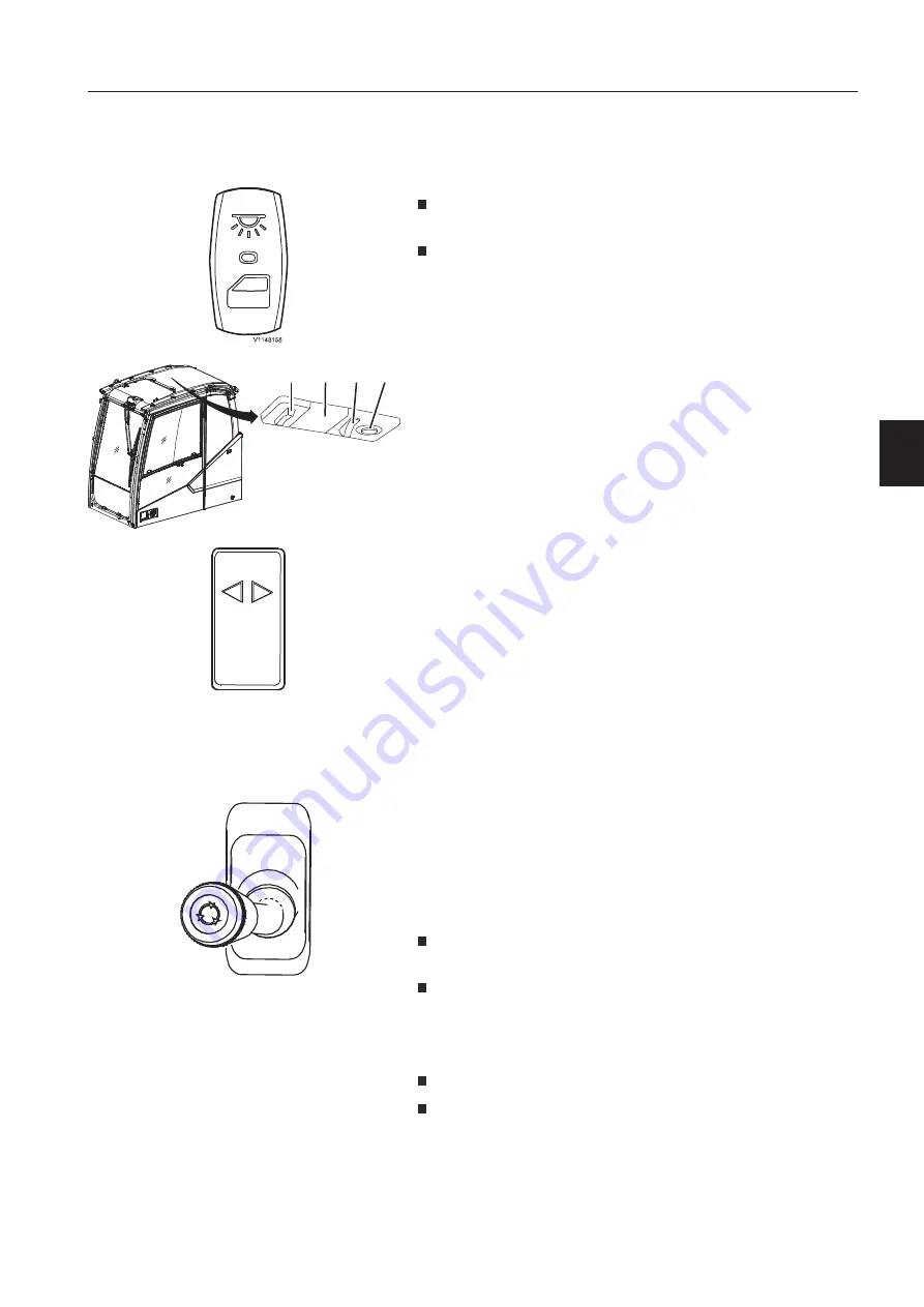
Press down the upper end of the switch to turn on the interior
light.
If the lower end of the switch is pressed down the interior light
will be turned on when the cab door is open. After closing the
cab door, the interior light will be turned off automatically.
Only when the upper end of the interior light switch is pressed
down, the switch (A) for the lamp (B) on the cab ceiling will work.
The reading light (D) can be turned on with the switch (C)
regardless of the interior light switch.
3.
.
Tra
a
i
i
l
l
e
e
r
r
fl
l
a
a
s
s
hi
i
n
n
g
g
in
n
d
d
i
i
c
c
at
t
o
o
r
r
(o
o
p
p
t
t
i
i
o
o
n
n
a
a
l
l
eq
q
u
u
i
i
p
p
m
m
e
e
n
n
t
t
)
)
This lamp shows the correct function of the trailer direction
indicators if trailer towing option is equipped, see page
234.
4
4
.
.
Co
o
n
n
t
t
r
r
o
o
l
l
le
e
v
v
er
r
fo
o
r
r
sta
a
b
b
i
i
l
l
i
i
s
s
er
r
le
e
g
g
s
s
/ sta
a
b
b
i
i
l
l
i
i
s
s
er
r
bl
l
a
a
d
d
e
e
/
du
u
m
m
p
p
tr
r
a
a
i
i
l
l
e
e
r
r
(o
o
n
n
l
l
y
y
wi
i
t
t
h
h
o
o
u
u
t
t
jo
o
y
y
sti
i
c
c
k con
n
t
t
r
r
o
o
l
l
l
l
e
e
d
d
sup
p
p
p
o
o
r
r
t
t
)
)
If
f
th
h
e mac
c
hin
n
e is
s
equ
u
i
i
p
p
p
p
e
e
d
d
wi
i
th
h
th
h
e op
p
t
t
i
i
o
o
n
n
a
a
l
l
joysti
i
ck con
n
tr
r
oll
l
ed
d
sup
p
p
p
o
o
rt fu
u
nc
c
ti
i
o
o
n
n
th
h
i
i
s
s
con
n
t
t
r
r
ol le
e
ver (4) is
s
no
o
t ex
x
isti
i
ng
g
,
,
in
n
th
h
i
i
s case
see
e
po
o
i
i
n
n
t
t
7A
A
/ 7B
B
fo
o
r
r
deta
a
iled de
e
s
s
crip
p
t
t
i
i
o
o
n
n
.
.
This control lever (4) is used for moving the stabiliser legs /
stabiliser blade up and down after having selected the function in
the IC (Instrument Cluster), see page
80.
Move the lever (4) forwards to lower stabiliser legs / stabiliser
blade.
Move the lever (4) backwards to raise stabiliser legs / stabiliser
blade.
Tr
r
ai
i
l
l
e
e
r li
i
f
f
t
t
i
i
n
n
g ac
c
ti
i
v
v
at
t
i
i
o
o
n
n
swi
i
t
t
c
c
h (10)
)
in combi
i
na
a
t
t
i
i
o
o
n
n
wit
t
h
h
th
h
is cont
t
r
r
ol
l
le
e
v
v
er
r
(4)
)
:
Press the upper end of the trailer lifting activation switch (10).
Move the lever (4) forwards to tilt the loading platform of the
attached trailer.
V1134956
A
B
C D
V1128465
V1182511
In
n
s
s
tr
r
u
u
m
m
e
e
n
n
t
t
pa
a
n
n
e
e
l
l
s
s
In
n
s
s
tr
r
u
u
m
m
e
e
n
n
t
t
pa
a
n
n
e
e
l
l
,
,
le
e
f
f
t
t
35
5
Summary of Contents for 322001
Page 7: ...5 5 ...
Page 146: ...Right mirrors 1 14 44 4 Op pe er ra at ti in ng g in ns str ru uc cti io on ns s ...
Page 172: ...1 170 Operating instructions Exhaust aftertreatment system ...
Page 357: ...S Specifications Dimensions 355 ...
Page 410: ......
Page 413: ......
Page 414: ...4 412 Alphabetical index Ref No 20052711 C Volvo Eskilstuna English ...


