


Group 21
Service procedures - engine
73
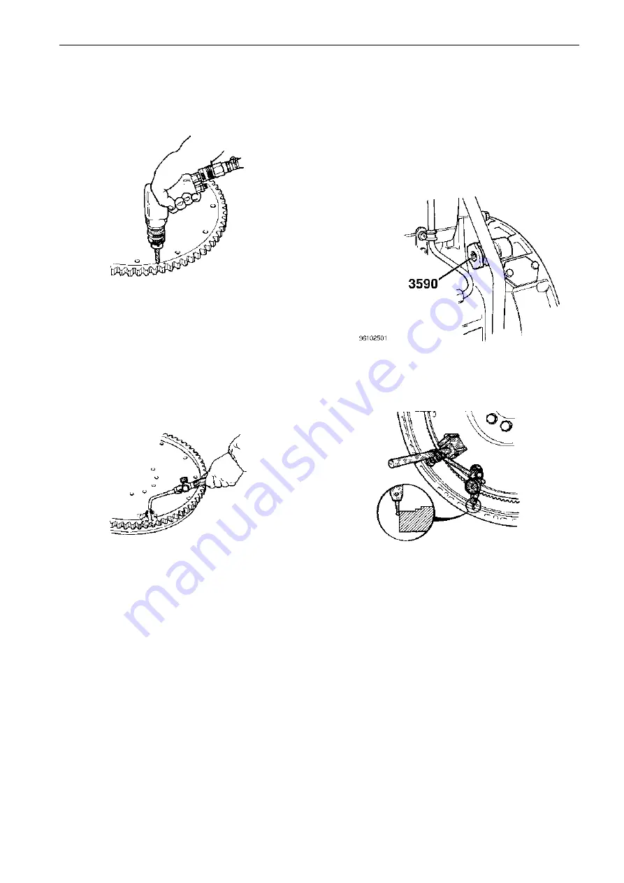
Ring gear, replacing
(Flywheel removed)
1
Flywheel casing, checking for
warp
Special tools: 998 9876, 999 9683, 999 9696, 999 3590
1
Clean the flywheel and flywheel casing.
Drill one or more holes in the ring gear and crack it with a
chisel. The ring gear can now be removed.
2
Use a steel brush to clean the contact surface on the fly-
wheel.
3
Evenly heat up the ring gear all the way round using a blow
torch. Take care not to overheat the ring gear since this
would result in material deterioration.
To check the amount of heat, polish the ring gear to a
shine at several places. At the correct temperature, these
bright spots will become blue (180-200°C/ 356-392°F)
and heating should be stopped.
4
Place the heated ring gear on the flywheel. Tap it into posi-
tion using a soft drift and a hammer. The ring gear should
then be allowed to cool slowly in air.
2
Fit cranking tool 999 3590.
3
Fit a dial indicator to a magnetic stand.
Mount the magnetic stand on the flywheel with the probe of
the dial indicator against the outer edge of the flywheel cas-
ing.
Crank the flywheel and calculate the difference between the
max and min. values.
Transfer the magnetic stand and dial indicator to the opposite
side of the flywheel and carry out the same measurement
procedure.
The difference between these two results must not exceed
0.20 mm (0.0079").
Summary of Contents for TAD1630G
Page 1: ...Workshop manual TAD1630G GE P V TAD1631G GE TID162AP TWD1620G GH TWD1630G GE P V TD164KAE ...
Page 2: ......
Page 18: ...Design and Function Group 21 16 Engine Design and Function ...
Page 80: ...Service procedures engine Group 21 78 Application of sealant to cylinder block ...
Page 162: ...160 ...
Page 164: ...7742302 English 10 2002 ...


