Service procedures - intake and exhaust systems
Group 22
122
WARNING! Do not use force.
13
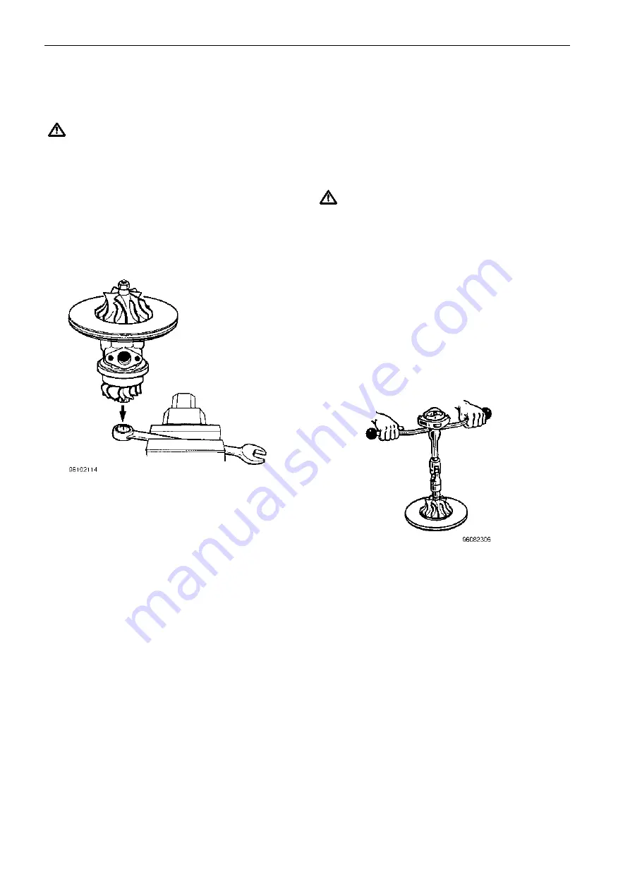
Clamp a suitable 12 point socket wrench in the vise with the
socket axis vertical. Place the bearing housing in the socket.
15
Fit the insert assembly into the bearing housing. Apply mod-
erate pressure to correctly seat the insert (43).
Note: It may be necessary to use a small, soft mallet.
16
Using circlip pliers, fit the large circlip (66). Place the bevel-
led side facing up.
WARNING! Extreme caution is required during fitting.
17
Fit the compressor wheel (7). Fit the compressor wheel lock-
nut (61) and tighten down. Torque 40.7 Nm (30.0 ft-lb).
Note: Use a T-handle torque wrench together with a univer-
sal joint to avoid side-loading the turbine wheel shaft.
18
Referring to the marks made previously, fit the bearing hous-
ing using the V-band clamp (28).
19
Check the axial and radial clearance. See section ”Checking
bearing clearance”.
20
Referring to the marks made previously, fit the compressor
cover to the bearing housing using the screws and washers.
Finally check that the shaft and wheels rotate freely.
14
Fit the thrust bearing (12) and thrust flange (36). Fit the oil
deflector (33) with the angled edge facing down. Fit a new
piston ring (16) to the oil slinger (31) and fit the oil slinger into
the bearing housing. Fit the O-ring (32).
12
Gently slide the shaft and wheel into the bearing housing.
Apply moderate pressure and a slight rotation to allow the
piston ring to centralize and enter the chamfered bore of the
bearing housing.
Summary of Contents for TAD1630G
Page 1: ...Workshop manual TAD1630G GE P V TAD1631G GE TID162AP TWD1620G GH TWD1630G GE P V TD164KAE ...
Page 2: ......
Page 18: ...Design and Function Group 21 16 Engine Design and Function ...
Page 80: ...Service procedures engine Group 21 78 Application of sealant to cylinder block ...
Page 162: ...160 ...
Page 164: ...7742302 English 10 2002 ...


