36
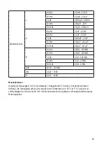
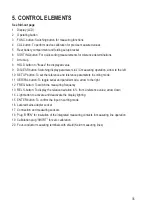
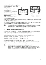
5.1. DISPLAY INDICATIONS AND SYMBOLS
A
Bar chart shows utilisation of the measured range in %
B Function and operating displays
Ext-Power
shows mains unit operation
Sorting
shows sorting mode
CAL
shows calibration mode
Tol
shows the pre-set tolerance range for sorting
120 100 KHz shows the measuring frequency
Battery symbol shows the battery status in battery operation
C Main parameter for measuring operation
s = serial for serial circuits in AC operation (Ls, Cs, Rs)
p = parallel for parallel circuits in AC operation (Lp, Cp, Rp)
DCR = direct current resistance (DC)
D Symbol for active automatic deactivation
E Measuring
functions
HOLD
Data hold is active, the displayed measured value is stored
AUTO
Automatic measuring operation with pre-selection of the measuring parameter (L, C, R)
AUTO
LCR Smart automatic measuring operation without pre-selection of the measuring parameter
RANGE:
Range display in sorting mode
REL
Reference value display mode
F
Main display with measuring units
G Sub-display with measuring units
H Subfunctions for the subdisplay
ESR
Equivalent serial resistor
RP
Equivalent parallel resistor
DQ
θ
D = dissipation factor , Q = quality,
θ
= phase angle


