40
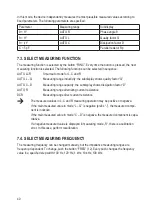
In this mode, the device independently measures the most plausible measured values according to
fi
xed parameters. The following parameters are speci
fi
ed:
Parameter
Measuring range
Subdisplay
θ
< 11°
AUTO R
Phase angle
θ
θ
> 11°
AUTO L
Quality factor Q
θ
< -11°
AUTO C
Dissipation factor D
C < 5 pF
Parallel resistor Rp
7.3. SELECT MEASURING FUNCTION
The measuring function is selected by the button “FUNC”. Every time the button is pressed, the next
measuring function is selected. The following functions can be selected in sequence:
AUTO LCR
Smart auto mode for L, C and R
AUTO L – Q
Measuring range inductivity; the subdisplay shows quality factor “Q”
AUTO C – D
Measuring range capacity; the subdisplay shows dissipation factor “D”
AUTO R
Measuring range alternating current resistance
DCR
Measuring range direct current resistance
The measured values in L, C and R measuring operation may be positive or negative.
If the main measured value in mode “L – Q” is negative (pre
fi
x “-”), the measured compo-
nent is inductive.
If the main measured value in mode “C – D” is negative, the measured component is capa-
citative.
If a negative measured value is displayed in measuring mode „R“, there is a calibration
error. In this case, perform recalibration.
7.4. SELECT MEASURING FREQUENCY
The measuring frequency can be changed manually, but the impedance measuring ranges are
frequency-dependent. To change, push the button “FREQ” (12). Every push changes the frequency
value in a speci
fi
ed step width: 100 Hz, 120 Hz, 1 kHz, 10 kHz, 100 kHz.


