15
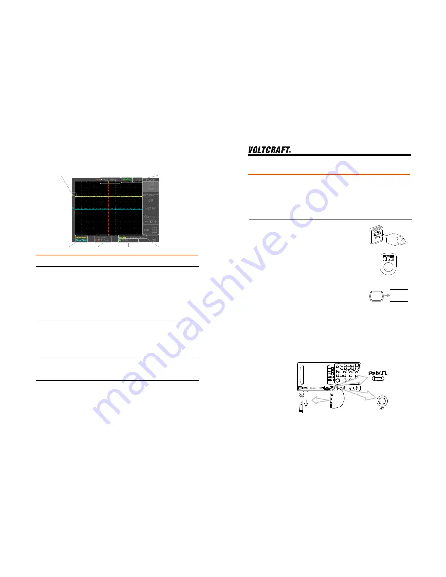
Display
Waveform marker
Vertical status Horizontal status
Frequency Trigger condition
Waveform position Trigger status Acquisition
Menu
Waveforms
Channel
1:
Yellow
Channel
2:
Blue
Trigger
status Trig’d
A signal is being triggered
Trig?
Waiting for a trigger condition
Auto
Updating the input signal
regardless of trigger conditions
STOP
Triggering is stopped
For trigger setting details, see page61.
Updates the input signal frequency (the trigger
source signal) in real-time.
Input signal
frequency
“< 20Hz” Indicates that the signal frequency is less
than the lower frequency limit (20Hz) and thus not
accurate.
Trigger
configuration
Shows the trigger source, type, and slope. In case
of the Video trigger, shows the trigger source and
polarity.
Horizontal status
Vertical status
Shows the channel configurations: coupling mode,
vertical scale, and horizontal scale.
DSO-4000 User Manual
16
Setting up the Oscilloscope
Background
This section describes how to set up the
oscilloscope properly including connecting a
signal, adjusting the scale, and compensating the
probe. Before operating the oscilloscope in a new
environment, run these steps to make sure the
oscilloscope is functionally stable.
Procedure
1. Connect the power cord.
2. Press the power switch. The
display will become active
in approximately 10
seconds.
3. Reset the system by recalling
the factory settings. Press
the Save/Recall key, then
Default Setup
. For details of
factory settings, see page32.
Default
Setup
Save/Recall
4. Connect the probe between the Channel1 input
terminal and probe compensation signal output
(2Vp-p, 1kHz square wave).
5. Set the probe attenuation to x10.
CH1
x1
x10


