1. System Structure and Set-up
AdminGuide-Voss12-1.docx
5
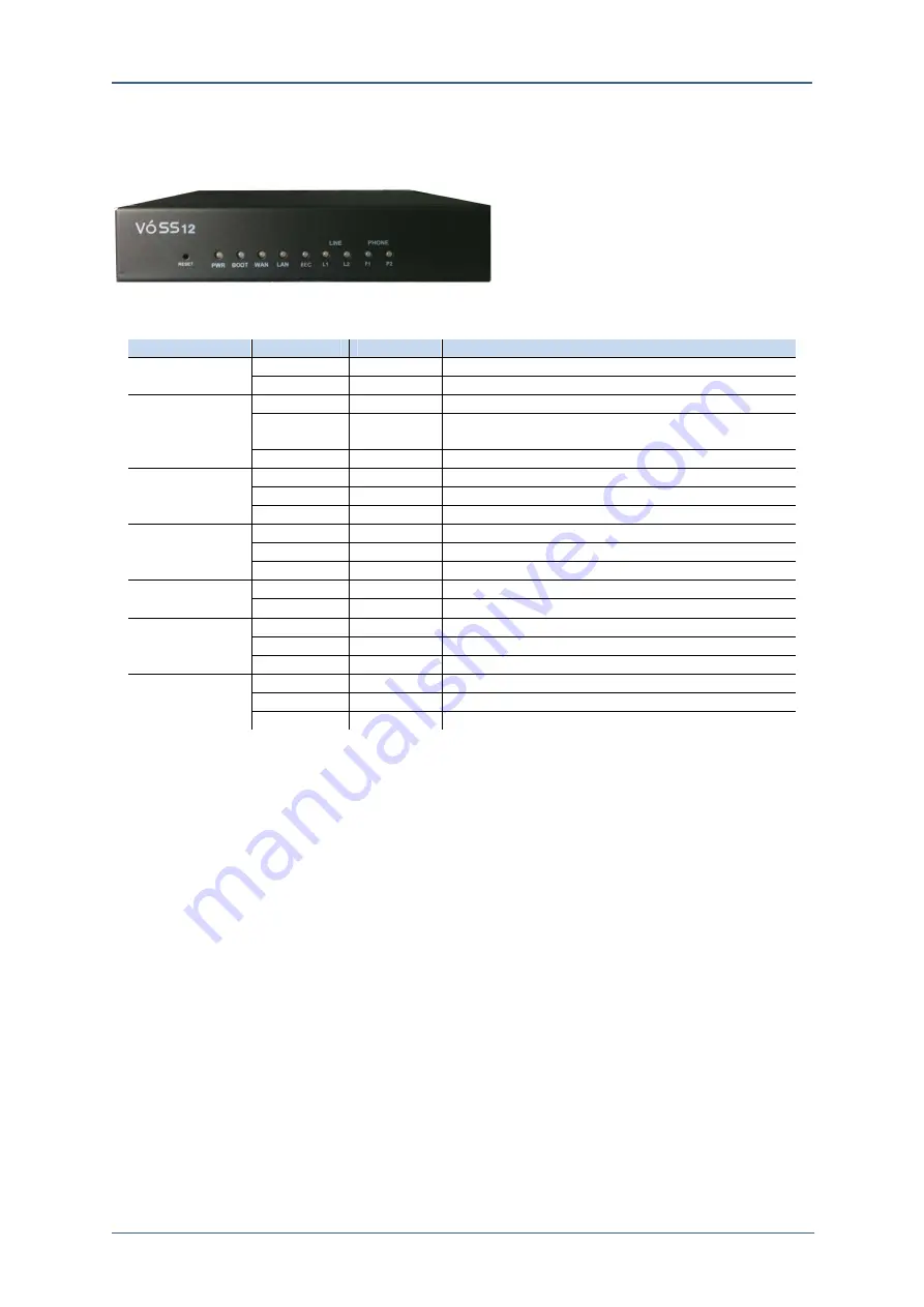
Figure 1-4. Front View of VOSS12
Table 1-2. LED Status Indication
LED
Green
Red
Description
Power
ON
OFF
Power Supply in good condition
OFF OFF
Powered
Off
Boot ON OFF
On
Booting
ON
ON
Will be turn off within 60Sec
Turning to Factory Default
Blinking OFF
Normal
Operation
WAN ON OFF
Link
up
Blinking
OFF
On Packet Communication
OFF OFF
Link
down
LAN ON OFF
Link
up
Blinking
OFF
On Packet Communication
OFF OFF
Link
down
USB ON OFF
USB
Mounting
Blinking Off
Voice
Recording
FXO
ON
OFF
TEL Line is connected
OFF
ON
TEL Line is busy
OFF
Blinking
TEL Line is ringing
FXS
ON
OFF
FXS port is held(Hold)
OFF
ON
FXS port is on the line(Busy)
OFF Blinking
Ringing
Factory Default
The small hole in the Left down on Figure 1-4. is the Factory default button which
is connected to a button inside the system. If the system lost IP address, you will
not be able to access the system. In that case, this button will return the system to
factory default status.
With a clip or the edge of pen press the button for 5 seconds then the system will
return to factory default. Once factory default is started, PWR LED turns on red
color and after completed factory default the RWR LED turns on green color and
reboots the system. Therefore, press the reset button until the PWR LED turns on
red color. The factory default IP address of VOSS12 is ‘192.168.1.10’. To connect
the system with your computer, connect a network cable to LAN port.
Line and Frame Earth Connection
The following Figure 1-1 shows the rear view of VOSS12 which is composed with
2 RJ-25 ports, 1 FXO ports, and 1 Life Line. The
‚
ⓐ
‛
indicates Frame
Ground(F.G) which protects users and the product from surge, lightening, and
electric shock. Therefore, the FE should be connected for safety purpose


