background image

VOKKERO GUARDIAN GUARDIAN SHOW   User Guide V1.0

26 / 32

EN

5- Advanced settings

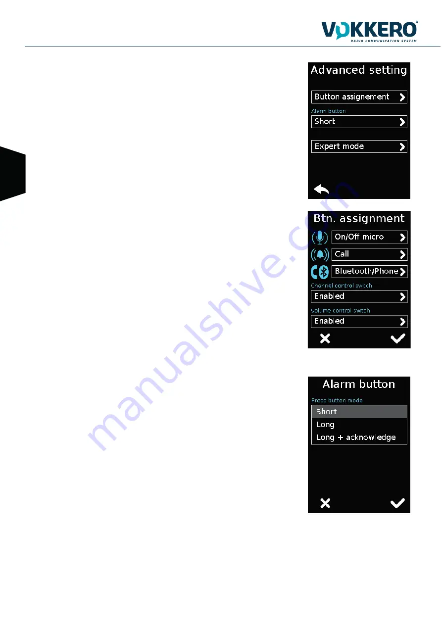
Provides access to the following options: 

- Assign buttons: to change the functions of the buttons on the terminal
- Alarm button: to change the press mode of the alarm button
- Expert mode:  Users cannot access this mode as it has settings that can disrupt the smooth-run-
ning of your VOKKERO® Guardian system.

5.1 Button assignment

Reset the functions of the terminal buttons or disable certain functions.

The microphone On / Off + Call + Bluetooth buttons can be switched or deactivated. Click the 
option shown by the pictogram on the button of your choice and reassign the chosen function to it. 

The Channel and Volume Selector triggers can only be turned on or off.

To reset the original functions, reload the terminal’s default settings via the «Factory Setup» menu.

5.2 Alarm button

Allows you to change the way you press the «Call» button to activate the alarm, regardless of the 
selected alarm mode (silencer, vibrator or sound + vibrator). 

The possible ways of activating the alarm are: 
- Short: 1 short press on the Call button triggers the alarm
- Long: 1 long press on the Call button triggers the alarm
- Long + Acknowledgment: 1 long press on the Call button triggers a loop alarm. To stop the alarm, 
press again continuously on the same button from one of the network terminals.

Summary of Contents for GUARDIAN SHOW

Page 1: ...VOKKERO www vokkero com VOGO 101 place Pierre Duhem Immeuble Les Centuries II 34000 Montpellier France www vokkero com VOKKERO GUARDIAN User Guide Version 1 0 211493 GUARDIAN SHOW ...

Page 2: ...VOKKERO GUARDIAN GUARDIAN SHOW User Guide V1 0 2 32 EN ENGLISH ...

Page 3: ...rights to this document and the information contained herein Reproduction use or disclosure to third parties without express permission is strictly prohibited Copyright 2016 VOKKERO VOKKERO is a registered trademark in the EU and other countris TECHNICAL SUPPORT Website Our website contains a lot of useful information information on modules and wireless modems user guides and configuration softwar...

Page 4: ...ndards and technical specifications have been applied Title Date of standard specification EN 300 220 2 V3 1 1 2017 02 EN 300 422 1 V2 1 1 2017 01 EN 303 204 V2 1 2 2016 09 EN 300 328 V2 1 1 2016 11 EN 301 489 1 V2 1 1 2016 11 EN 301 489 3 V2 1 0 2016 09 EN 301 489 9 V2 1 0 2016 09 EN 301 489 17 V3 1 1 2016 09 EN 60950 1 2006 A1 2009 A2 2013 A12 2011 2009 A12 2011 EN 50566 2013 EN 62209 2 2010 The...

Page 5: ...50 20 Yes EU8 863 500 10 No EU9 864 500 10 No EU10 868 300 14 No No Usable in all European Community countries without restrictions Yes RESTRICTIONS in some EU countries For channels with usage restrictions refer to appendix 1 National Implementation of recommendation ERC REC 70 03 available on the ECO European Communication Office website https www ecodocdb dk document category ECC_Recommendation...

Page 6: ...ct of the declaration described above is in conformity with the relevant Union harmonisation legislation Directive 2014 30 UE CEM Directive 2014 35 UE basse tension The following harmonised standards and technical specifications have been applied Title Date of standard specification EN 301 489 1 V2 1 1 2016 11 EN 301 489 3 V2 1 0 2016 09 EN 301 489 9 V2 1 0 2016 09 EN 301 489 17 V3 1 1 2016 09 EN ...

Page 7: ...r one of its products without notice in writing and urges its customers to make sure that the information they have is valid VOKKERO configuration software and programs are available free of charge in a non modifiable version VOKKERO can make no guarantees including guarantees concerning suitability and applicability for a certain type of application Under no circumstances can the manufacturer or ...

Page 8: ...nstructions in the manual The safety of this product is only guaranteed when it is used in accordance with its purpose Maintenance should only be carried out by qualified persons Please note Do not install the equipment close to a heat source or in damp conditions Please note When the equipment is open do not carry out any operations other than the ones set out in this document Please note Do not ...

Page 9: ...xplosion After use the batteries must be disposed of at an appropriate recycling centre They must not be thrown away to degrade in the environment When batteries are replaced the device must be corectly implemented Warning for Switzerland the annex 4 10 of SR 814 013 Standad must be applied for batteries This symbol on the devode or its packaging means the use of a DC voltage RECOMMANDATIONS REGAR...

Page 10: ... menu via a touchscreen The configurator must be connected to the power supply otherwise it will not work and up to 4 extensions units can be chained with the configurator 1 SYSTEM INSTALLATION PROCEDURE Connect the power supply to the configurator or at the back of last chained charging unit if several are connected in a row Connect the power supply to the mains Insert the VOKKERO Guardian termin...

Page 11: ...h func tion when Menu is open Channel selec tor Changes the communication channel or group Hold to enter Menu and trigger up and down to browse Bluetooth Pairs a bluetooth device Optional LED Device on and Network connection LCD Screen Optional sleep mode Belt clip Battery Removable battery unit can be charged separately General Specifications Value Supply voltage 3 7V nominal Maximum consumption ...

Page 12: ...67A 50 60Hz more than 10 terminals charging Operating temperature 5 C 40 C Dimensions Configurator Charger 337 x 95 x 58mm Dimension extension 216 x 95 58mm Weight configurator charger 470g Weight extension 310g LED Terminal charge Red no terminal or defective terminal Orange terminal charging Vert terminal charged Screen Configurator display screen Power supply connector Power jack Battery Chargi...

Page 13: ...to a network Channel or Group Shows the active Channel or Group Role Indicates the role of the terminal M Master role 2 to 16 Other roles Microphone status Either On or no microphone connec ted or microphone Off 3 1 LCD Screen Icons by Default 3 2 IMPORTANT about M role When setting up your Guardian Show system the first step consists in attributing the Master role M to a single terminal of your c...

Page 14: ...eadset it should connect easily if this is not the case check the headset to make sure it isn t damaged 3 3 2 Removing the headset Pull on the ring of the headset to release the connector switch and pull out the Lemo connector Do not attempt to remove the headset by pulling or twisting or turning the connector s chassis Use the Mic icon on the terminal screen to make sure that the headset is prope...

Page 15: ...in groups 1 to 4 can only hear and speak with the members of their group Group 0 terminals Gr0 can hear and speak with all groups When you change groups a beep in the accessory s loudspeaker signals that the terminal has taken the change of group into account A double beep signals that you have reached the upper or lower limit Check the number of the selected group on the terminal s LCD 3 4 Termin...

Page 16: ...al screen displays the Call icon together with the call sender s name Note if the GROUP function is active then the notification is only sent to group of which the call sender belongs in addition to Group 0 3 4 6 Bluetooth Option The Bluetooth function is used to send and make phone calls whilst remaining on the work device This function can also be used to connect a Bluetooth wireless headset You...

Page 17: ... s LCD screen displays a blinking icon for the duration of the call Receiving a phone call Si vous recevez un appel téléphonique le terminal vibre et un double bip est émis dans l accessoire micro casque To answer the call press the Bluetooth button To end the call press the Bluetooth button During the phone call the terminal s LCD screen displays a blinking icon for the duration of the call Switc...

Page 18: ...the back of the product keep pushing until you hear the locking clip Attaching the belt clip Slide the belt clip into the slot keep pushing until you hear the locking clip NOTE the terminal must always be positioned at the belt using the clip provided or on the arm via a armband ensuring a distance of 11mm from the body 3 4 8 Belt clip Removing the belt clip The terminal comes with a belt clip How...

Page 19: ...t Gate cannot be set to OFF in Live Mode see chapter 7 Note that when adjusting Gate level Side Tone is momentely activated Post Gate providing a clear feedback when searching for the most appropriate gate level 4 2 3 Side Tone Adjust the Side Tone between 3 different levels Side Tone can be heard only when Mic is activated Latch or PTT At maximum Side Tone level some external noises may be heard ...

Page 20: ...he release of the button mutes the mic Note that default setting is Latch for Rigging mode and PTT for Live and Studio modes Note that when using Live and Studio modes to set more than two terminals with Latch may input too much ambiant noise into the sys tem 4 2 8 LCD Choose between Always ON and Sleep When Sleep mode is selected LCD lits off 3 seconds after last command is used The LCD wakes up ...

Page 21: ...tch To turn it on the configurator must be connected to the power unit provided with the VOKKERO Guardian The configurator has a USB port for software updates The configurator screen is a high resistance touchs creen The configurator can also be used to download products Immediately upon starting up the system the configurator displays the VOKKERO logo with the firmware version of the configurator...

Page 22: ...imilar frequencies as referees coms on the pitch 6 3 Channel Selection Browse in the chennel menu and select your preffered channel here Confirm by ticking the box Start the configuration by selecting GO on the screen and then validating the confirmation screen the configuration starts If the configuration completes successfully the indication DONE displays Alternatively the indication ERROR displ...

Page 23: ...atency PTT Mode Voice Activity Detector OFF gate level off 7 users max including a potential Wireless Interface Live Ideal for live coms with cues Go and descending orders from director to technicians Ideal latency PTT Mode Voice Activity Detector OFF Hard gate level Unlimited users Rigging Ideal for stage trussing and fixture mounting in noisy environments Basic latency Latch mode hands free Voic...

Page 24: ...of the audio button in the middle of the terminal Alarm mode 3 defines the operating mode of the alarm Voice Priority Advanced Settings 5 Provides access to the following options Assignment buttons Alarm button Expert mode Version 6 Factory Setting 7 allows to reset the products to factory settings 1 Terminal name To change the name of the terminal you can use the available keyboard Three screens ...

Page 25: ...o Microphone Off If the microphone is Off press and hold this button to switch to Microphone On Push to mute The microphone is Off for as long as the button is pushed and held 3 Alarm Mode Whenever the product receives a call from another terminal or from a paired Blue tooth device it can notify the user depending on the configured mode The modes available are Silent Flashing screen only Vibration...

Page 26: ...ion shown by the pictogram on the button of your choice and reassign the chosen function to it The Channel and Volume Selector triggers can only be turned on or off To reset the original functions reload the terminal s default settings via the Factory Setup menu 5 2 Alarm button Allows you to change the way you press the Call button to activate the alarm regardless of the selected alarm mode silen...

Page 27: ... returns to the factory setting a product or all products connected to the configurator After selecting and validating your choice the configurator lets you know if the return to factory settings completed successfully To finalize the operation select the arrow on the bottom left hand side to return to the configu ration screen of the terminals ...

Page 28: ...ls are set in the same group group 0 Details of groups Group 0 Gr0 you can hear and talk with all groups Group 1 to 3 you can only hear and talk with members of that group in addition of the memebers of Group 0 9 2 Encryption The encryption key is used to make communications within a given system secure Only the devices using the same encryption key are authorized to communicate on the network Sev...

Page 29: ...rminal appear on the display Screen No 1 To configure a new software version on the terminals Once the USB key ready insere it into the dedicated USB port situated on the left located on the left side of the configurator Screen No 2 Once the USB key connected the available software version is displayed Screen No 3 If the USB key is empty or involves wrongs files you will read on the display Update...

Page 30: ...he version currently installed in the configurator appear on the display Screen No 1 To configure a new software version on the configurator Once the USB key ready insere it into the dedicated USB port situated on the left located on the left side of the configurator Screen No 2 Once the USB key connected the available software version is dis played Screen No 3 If the USB key is empty or involves ...

Page 31: ...lighting Slide the cursor from left and right to decrease and increase respectively screen lighting 2 Calibrating the touchscreen The configurator touchscreen is already calibrated in the factory you can howe ver calibrate your own touchscreen if you note a significant change in screen detection To do this carry out the following 5 steps Select each angle with the yellow poin ter then select the c...

Page 32: ...code can be modified or deactivated see screen below showing the options available in the Lock menu once the lock has been activated 3 Resetting the configurator functions In order to put the configurator back in factory mode and thus cancel all the configuration changes made pre viously do the following Unplug the configurator Reconnect the configurator When the configurator is switched on on the...

Reviews: