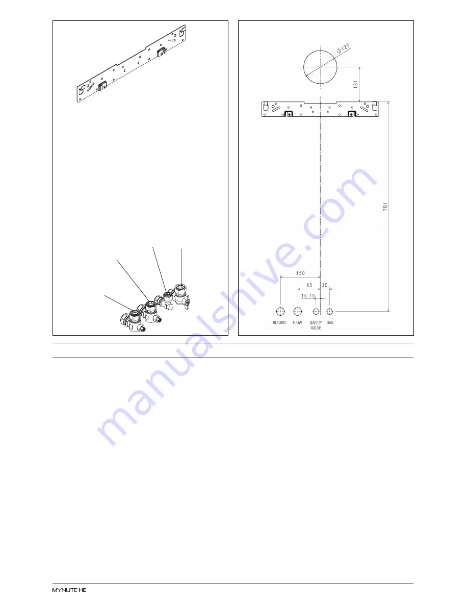
background image

7

Fig.  6A

Gas

cock

C/H flow

valve

C/H return

valve

Safety

valve outlet

Fig.  6B

SECTION 3A

GENERAL REQUIREMENTS (EIRE)

This appliance must be installed by a competent
person in accordance with and defined by, the
Standard Specification (Domestic Gas Installa-
tions) Declaration (I.S. 813).

3A.1

RELATED DOCUMENTS

The installation of this boiler must be in accord-
ance with the relevant requirements of the local
building regulations, the current ETCI National
Rules for Electrical Installations, and the bylaws
of the local water undertaking.
It should be in accordance also with any relevant
requirements of the local and/or district authority.

3A.2

LOCATION OF APPLIANCE

The appliance may be installed in any room or
internal space, although particular attention is
drawn to the requirements of the current ETCI Na-
tional Rules for Electrical Installations, and I.S.
813, Annex K.
When an appliance is installed in a room or internal
space containing a bath or shower, the appliance
or any control pertaining to it must not be within
reach of a person using the bath or shower.
The location chosen for the appliance must permit
the provision of a safe and satisfactory flue and
termination. The location must also permit an
adequate air supply for combustion purposes and

an adequate space for servicing and air circulation
around the appliance. Where the installation of the
appliance will be in an unusual location special
procedures may be necessary, refer to I.S. 813 for
detailed guidance on this aspect. A compartment
used to enclose the appliance must be designed
and constructed specifically for this purpose. An
existing compartment/cupboard may be utilised
provided that it is modified to suit. This appliance
is not suitable for external installation.

3A.3

GAS SUPPLY

The gas meter - as supplied by the gas supplier -
must be checked to ensure that it is of adequate
size to deal with the maximum rated input of all the
appliances that it serves.  Installation pipes must
be fitted in accordance with I.S. 813.
Pipe work from the meter to the appliance must
be of adequate size. Pipes of a smaller size than
the appliance gas inlet connection must not be
used. The installation must be tested for sound-
ness in accordance with I.S. 813.
If the gas supply serves more than one appliance,
it must be ensured that an adequate supply is
maintained to each appliance when they are in
use at the same time.

Summary of Contents for MYNUTE 35HE

Page 1: ...Installation Servicing Instructions THESEINSTRUCTIONS TO BE RETAINED BY USER 0694 0694BQ0479...

Page 2: ...on analysis 15 5 8 Final flushing of the heating system 15 5 9 Setting the boiler operating temperature 15 5 10 Setting the system design pressure 16 5 11 Regulating the central heating system 16 5 12...

Page 3: ...ansion ves sel safety valve pressure gauge and automatic by pass The35HEisproducedasaroomsealed categoryII2H3P appliance suitableforinternalwallmountingapplications only It is provided with a fan powe...

Page 4: ...try to ensure flame stability at the burner Once suc cessful ignition has been achieved the electronic circuitryincreasesthegasrateto75 foraperiod of 15 minutes Thereafter the boiler s output will eit...

Page 5: ...ions Height 845 mm Width 453 mm Depth 359 mm Dry weight Kg 43 0 2 5 Clearances Sides 12 mm Top 150 mm from casing or 25 mm above flue elbow whichever is applicable Bottom 150 mm Front 600 mm 2 6 Conne...

Page 6: ...tc 500 mm D Below gutter drain pipe etc 75 mm E Below eaves 200 mm F Below balcony car port roof etc 1200 mm G To the side of a soil drain pipe etc 150 mm H From internal external corner or boundary 3...

Page 7: ...entrally over the terminal Refer to BS 5440 Part 1 when the terminal is 0 5 metres or less below plastic guttering or 1 metre or less below painted eaves BS5440 PART 1 FLUES BS5440 PART 2 FLUES VENTIL...

Page 8: ...fuse The method of connection to the mains electricity supply must allow for com plete isolation from the supply The preferred method is by using a double pole switch with a contact separation of at...

Page 9: ...hosenfortheappliancemustpermit the provision of a safe and satisfactory flue and termination The location must also permit an adequateairsupplyforcombustionpurposesand anadequatespaceforservicingandai...

Page 10: ...he system has an unusually high water content it may be necessary to provide additional expansion capacity see 6 19 3A 6 6 FILLING POINT Amethodforinitialfillingofthesystemandreplacing water lost duri...

Page 11: ...te supplied carefully mark the position of the wall mounting bracket see fig 6 and flue hole if applicable 4 5 FITTING THE FLUE The top flue outlet permits both horizontal and verticalflueapplications...

Page 12: ...to ensurethatthecorrectsealismadewhenassem blingthefluesystem Connecttherequirednumber of flue extensions or bends up to the maximum equivalentfluelength totheflueterminal seefig 7 8 The flue system...

Page 13: ...the dedi cated concentric flue kit for termination It is essential that the installation of the twin flue system be carried out in strict accordance with these instructions GUIDANCE NOTES ONTWIN FLUE...

Page 14: ...in flue pipes must be pushed 50mm onto the male spigots of the concentric to twin converter NOTE Seal the flue terminal assembly to the wall using cement or a suitable alternative that will provide sa...

Page 15: ...nlet of the valve and tighten both nuts NOTE Itwillbenecessarytocalculatethediameterofthe gas supply pipe to ensure the appliance has an adequate supply of gas 4 6 2 FLOW RETURN fig 6 The appliance is...

Page 16: ...B cover C Fig 15 Optional devices 24V terminal block Mains 230V terminal block 4 7 2 APPLIANCETERMINALBLOCK Theapplianceterminalblockislocatedontherear of the control fascia Remove the casing as descr...

Page 17: ...ensure the proper electrical checks have been carried out see 7 8 particularly continuity polarity and resistance to earth ensure the 3 AMP fuse supplied with the appliance has been fitted ensure the...

Page 18: ...LY SECURED ENSURE ALL PIPE WORK IS RE CHECKED FORSOUNDNESS RE FIT APPLIANCE CASING COMPLETEBENCHMARKCHECKLIST FOR UK ONLY Complete details of the boiler controls installa tionandcommissioningintheBenc...

Page 19: ...ugh it is anticipated that this appliance will give years of reliable trouble free service the life spanofcomponentswillbedeterminedbyfactors such as operating conditions and usage Should the applianc...

Page 20: ...rolfasciaupwardandrotate it Locateandremovethescrews A whichsecure the PCBcover pushtheclips B andremovecover after carefullytakingnoteofallwiringconnections discon nect all wiring from the PCB locate...

Page 21: ...re it is replaced correctly Replace in the reverse order 6 16 MAIN HEAT EXCHANGER fig 29 30 Carry out component removal procedure as de scribed in 6 4 Unclip and remove the three air chambercovers fro...

Page 22: ...tandleft side covers Disconnect the fan transformer wiring Locateandremovethe2screws D thatsecurethefan transformer to the air box plate cut the two cable ties previewedonheat shrinkableinsulatorsthat...

Page 23: ...of the primary thermistor reaches 30 C There after the pump fan will over run for 30 sec onds Pump anti block cycle when there has been noheatingorHWrequestfor24 hours theanti block cycle is activate...

Page 24: ...ee fig 36 Push MODE button and selecttheadjustparameterspasswordbyturning the RH right hand encoder and confirm it by pushingMODEbutton Thefollowingfunctionsare available in this mode 7 4 1 GAS TYPE S...

Page 25: ...liance however you must check that the CO2 values are set correctly see 7 4 Insert the flue gas analyser probe into the flue gas test point see fig 35 Operate the boiler in HH LL and compare the value...

Page 26: ...ition 13 check the wiring harness 23 check the wiring harness 25 high limit flow temperature probe 27 high limit return temperature probe 31 internal fault 35 fan error 36 internal fault 41 low water...

Page 27: ...odes 6x appear if a problem exists with the secondary DHW thermistor Check thermistor Check wiring continuity FAULT CODES 5x Fault codes 5x appear if a problem with the main board exists Check paramet...

Page 28: ...3600 1 25 Differential heating positive C 2 10 1 6 26 Differential heating negative C 2 10 1 6 28 CH timer force burner 75 after CH start Min 0 20 1 15 29 CH timer blocking time CH Min 0 20 1 5 30 CH...

Page 29: ...win channel programmers figs 40 41 The appliance can be used in conjunction with typi cal S Plan Y Plansystems see8 4 1 8 4 2 please contact Vokera technical should you requirefurtherdetailedinstructi...

Page 30: ...28 8 4 1 Y PLANWITH EXTERNALTWIN CHANNEL PROGRAMMER fig 40 8 4 2 S PLANWITH EXTERNALTWIN CHANNEL PROGRAMMER fig 41 Fig 40 Fig 41...

Page 31: ...S Outside sensor WPS Water pressure sensor FS Flow termoster RS Return termoster AE01A P1 Master board AE01A P2 Ausiliary board controll M0T2B Motor control board AC0X Display board K9 Pump relay K13...

Page 32: ...cover assembly 10025842 26 Instrumental panel 10027949 31 Case 10026241 38 Driver PCB 10027200 90 Fuse 3478 226 Edge clip 5128 300 Wiring harness 10026341 301 Wiring harness 10027953 302 Wiring harnes...

Page 33: ...ctions cover 10027685 63 Pipe 10026228 105 Pressure transductor 10027132 201 Washer 5026 265 Washer 5236 266 Washer 5237 288 Washer 6898 290 Clip 2165 351 Nut 1823 353 Nut 1824 432 Clip 10024958 435 C...

Page 34: ...6338 6 Pipe 10026264 7 Pipe 10027317 9 Pipe 10027318 10 Pipe 10027146 17 Air vent bottle 10026275 25 Siphon 10027190 26 Flexible pipe 10027191 27 Flexible pipe 10027192 48 Pipe 10027321 66 Flexible pi...

Page 35: ...veyor 10026309 39 Gas pipe 10027196 46 Gas diaphragm 10027162 46 Gas diaphragm 2111 67 Washer 10026322 69 Tryton 10027089 72 Mixer 10024295 200 Washer 5023 479 Transformer 10026237 480 Transformer 100...

Page 36: ...r assembly 01005369 7 Conveyor assembly 10026310 12 Flue drain connection 10026311 27 Fumes testing connection screw 10020625 475 Washer 10026323 482 Washer 10026366 487 Washer 10026345 509 Limit ther...

Page 37: ...themaximumpower the CO2 readingshouldbeasshowninthetableabove If the CO2 reading is correct press the MODE button to exit the maximum setting If the CO2 reading is incorrect the maximum gas pressure m...

Page 38: ...OW RATE lts min FOR CONDENSING BOILERS ONLY CONFIRM THE FOLLOWING THE CONDENSATE DRAIN HAS BEEN INSTALLED IN ACCORDANCE WITH THE MANUFACTURER S INSTRUCTIONS YES FOR ALL INSTALLATIONS CONFIRM THE FOLLO...

Page 39: ...CARD SERIAL No COMMENTS SIGNATURE SERVICE 3 DATE ENGINEER NAME COMPANY NAME TEL No CORGI ID CARD SERIAL No COMMENTS SIGNATURE SERVICE 4 DATE ENGINEER NAME COMPANY NAME TEL No CORGI ID CARD SERIAL No...

Page 40: ...0 333 0520 Fax 01442 281403 After Sales Service Tel 0870 333 0220 Vok ra Ireland West Court Callan Co Kilkenny Tel 05677 55057 Fax 05677 55060 Vok ra Ltd reserve the right to change the specifications...

Reviews: