


23
Symptom
No display/
ignition
No hot water
No heating
Possible causes
Check wiring.
Check electrical supply
Check external controls
Check external controls
Fault code
10
30
40
70/72/74
Possible causes
Check gas supply, check flue system,
check polarity.
Debris in flue system.
Check system pressure, check for air in boiler/
system.
Check service valves, check pump, check
external zone valves.
●
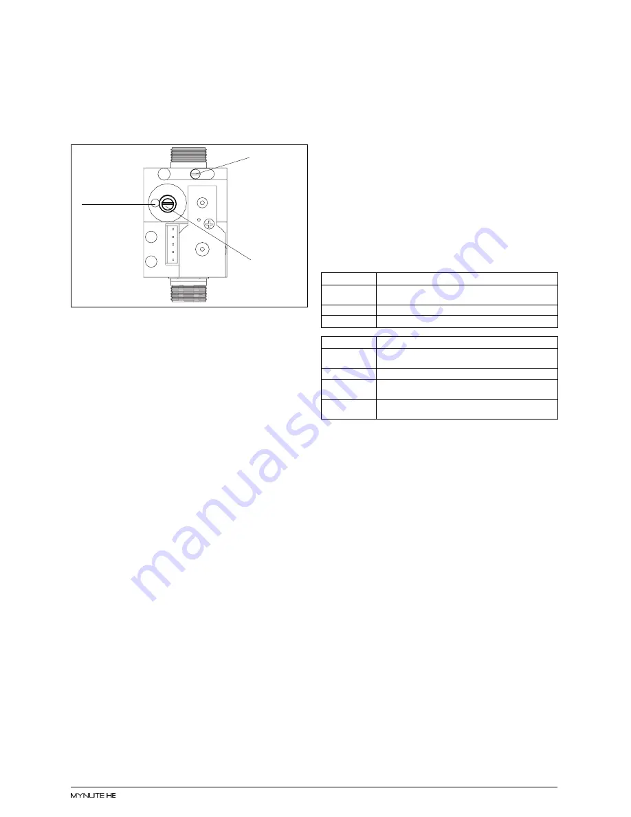
using a suitable screwdriver, very slowly turn the
maximum adjustment screw (see fig. 38) - clock-
wise to decrease, counter clockwise to increase
- until the correct value is displayed on the CO
2
analyser (allow time for the analyser to stabi-
lise).
IMPORTANT
A GAS SOUNDNESS CHECK MUST BE CAR-
RIED OUT.
7.4.7
GAS VALVE MINIMUM SETTING - LL
Select the LL parameter by turning the RH (right-
hand) encoder. The boiler starts at the minimum
power, the CO
2
reading should be as shown in the
table above.
If the CO
2
reading is correct, pass to gas valve
final setting (7.4.8). If the CO
2
reading is incorrect,
the minimum gas pressure must be adjusted as
follows:
●
using a suitable screwdriver, very slowly turn the
minimum adjustment screw (see fig. 38) - clock-
wise to increase, counter clockwise to decrease
- until the correct value is displayed on the CO
2
analyser (allow time for the analyser to stabi-
lise).
7.4.8
GAS VALVE FINAL SETTING - MM
Select the MM parameter by turning the RH (right-
hand) encoder, the boiler starts at the medium
power and it is possible to change the power of the
boiler turning the CH temperature control in order
to check the CO
2
in the overall range of the boiler.
7.4.9
MINIMUM OUTPUT CH (FAN SPEED) - 24
Select the parameter 24 by turning the RH (right-
hand) encoder. Push MODE button, it is possible
to modify the minimum fan speed by turning the
RH (right-hand) encoder. Push MODE button to
store the value.
7.5
COMBUSTION ANALYSIS TEST
A combustion analysis check can easily be car-
ried out on the appliance via the test points located
on the top of the appliance, however you must
check that the CO
2
values are set correctly (see 7.4).
●
Insert the flue gas analyser probe into the flue
gas test point (see fig. 35).
●
Operate the boiler in HH - LL and compare the
values with those shown in 7.4.6. If different
adjust the gas valve according to 7.4.6. and
7.4.7.
7.6
CHECKING THE EXPANSION VESSEL
Carry out the component removal procedure as
described in 6.4. You must ensure that the boiler
is completely drained of water.
Using a suitable pressure gauge, remove dust cap
on expansion vessel and check the charge pres-
sure. The correct charge pressure should be 1.0
bar ± 0.1 bar. If the charge pressure is less, use
a suitable pump to increase the charge.
NOTE
You must ensure the drain valve is in the open
position whilst re-charging takes place. Replace
the dust cap and carry out the relevant commis-
sioning procedure (section 5).
7.7
EXTERNAL FAULTS
Before carrying out any faultfinding or component
replacement, ensure the fault is not attributable to
any aspect of the installation.
7.7.1
INSTALLATION FAULTS
7.8
ELECTRICAL CHECKS
Any electrical checks must be carried out by a
suitably qualified person.
7.8.1
EARTH CONTINUITY TEST
Isolate the appliance from the electrical supply,
and, using a suitable multi-meter, carry out a
resistance test. Connect test leads between an
appliance earth point and the earth wire of the
appliance supply cable. The resistance should be
less than 1 OHM. If the resistance is greater than
1 OHM check all earth wires and connectors for
continuity and integrity.
7.8.2
SHORT CIRCUIT CHECK
Isolate the appliance from the electrical supply
and, using a suitable multi-meter, carry out a short
circuit test between the Live & Neutral connec-
tions at the appliance terminal strip (fig.17).
Repeat above test on the Live & Earth connec-
tions at the appliance terminal strip (fig.17).
NOTE
Should it be found that the fuse has failed but no
fault is indicated, a detailed continuity check will
be required to trace the fault. A visual inspection
of components may also assist in locating the
fault.
Fig. 38
Maximum
screw
Minimum
screw
Compensation
pipe connection