VMAC
– Vehicle Mounted Air Compressors
Toll Free:
1-888-241-2289
Fax: 1-250-740-3201
64
□
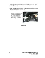
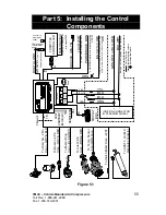
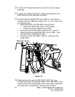
Find the ignition switch connector on the left side of the steering
column, as shown in
Figure 5.6. Of its 6 wires, locate:
•
Pin 4 wire green-red or blue-red (Middle)
•
Pin 7 wire blue-white (Bottom)
□
Cut the wire coloured green-red or blue-red and solder then seal
the yellow and orange pigtails to the two new ends of this wire.
•
Yellow pigtail solders onto wire going into dash.
•
Orange pigtail solders onto wire going to the
connector/steering wheel.
□
Cut the blue-white wire and solder then seal
the two “blue”
pigtails to the two ends of this wire. It doesn’t matter which pigtail
is attached where for this wire.
□
Route the four (4) wires towards the igni0tion connector.
□
Connect these wires by matching the colours and labels to the
pigtails soldered earlier.
•
Yellow wires connect together
•
Orange wires connect together
•
Blue wires labeled connect together
5.4 Completing and Testing the Installation
□
Cover all under hood and under chassis wiring with plastic loom.
Secure the harnesses with nylon ties. Avoid wiring contact with
hot or moving parts.
□
Route the loomed harness above the coolant lines towards the
front of the truck. Follow the radiator coolant lines across the
radiator towards the compressor.
□
Pull all excess wiring back into the cab, bundle the wiring
together and tie it up out of the way under the dash.
□
Use remaining loom to cover wires inside of cab, such as:
•
Wires connecting VR Throttle Controller to Control Box.
•
Wires connecting relays to START/STOP splices.
•
Any remaining wires or wire-bundles
Summary of Contents for VR70
Page 2: ......
Page 74: ...This page intentionally left blank...
Page 75: ...This page intentionally left blank...
Page 76: ...This page intentionally left blank...
Page 77: ...This page intentionally left blank...
Page 79: ......

