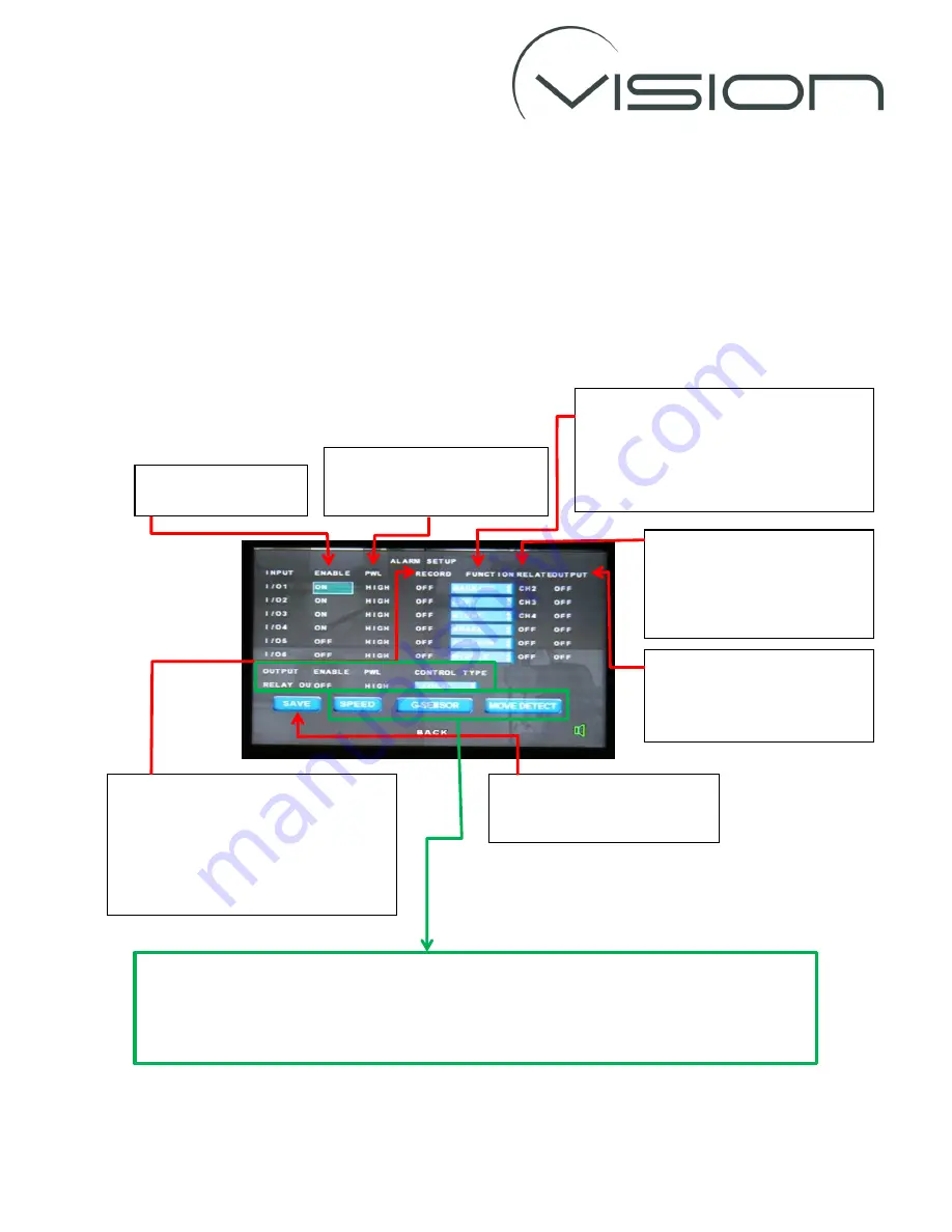
ALARM SET
Use the
ALARM SET
to configure the alarm functionality of the DVR.
The DVR has 6 Alarm Inputs (I/O 1-6) - which correspond to the white wires on the Interface
Connector labelled AL1-6 respectively, and 1 Alarm output.
Note the Alarms Inputs also have a turn off delay feature so can be connected directly to an
indicator light circuit. The alarms will activated if “see” a voltage >3.5Volts.
As has been described previously use the arrow and ENTER buttons on the r/c to highlight and
change the settings (unless otherwise described).
To use the
ALARM OUTPUT
,
SPEED
and
MOVE DETECT
functions please call Vision UK to ensure that
these options are configured - and the Interface Connector wired - correctly to provide the desired
functionality.
The
G-SENSOR
function is explained on the following page.
Set
ENABLE
to
ON
to
enable a specific alarm
To record an alarm file when an alarm is
activated set
RECORD
to
ON.
Alarm files should only be recorded for
important but infrequent events as
alarm files will not be overwritten and
can quickly fill up the available memory.
To activate an alarm when a
voltage is applied to the
trigger wire set
PWL
to
HIGH.
A
FUNCTION
name can be assigned to
individual alarms.
LEFT, RIGHT, BRAKE
descriptions will be
embedded with the recorded video when
the corresponding alarm is triggered.
The
RELATE
setting assigns a
Channel number to an alarm so
that when that alarm is
triggered the DVR will display
that channel on the AV output.
To turn on the DVR’s alarm
output when an alarm input is
triggered set the
OUTPUT
to
ON
.
Highlight the SAVE option and
press the ENTER button on the
r/c to save the changes.


