X
6.0 CONCENTRIC FLUE LAYOUT
PAGE 11
Y
A
B
X
Y
C
X
D
E
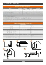
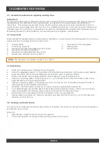
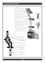
TABLE OF CONCENTRIC FLUE LAY OUT
Lay out
Illustration
X total in
Y total in
Restriction
min* max* min* max*
Indirect exterior wall outlet
A-B
1
5
0
5
None
Roof termination without elbows
C
2
12
from 3 meter
Roof termination with 45º elbows**
D
3
12
0
4
from X total + Y > 3 meter
Roof termination with 90º elbows***
E
1
12
0
2
from X + X1- Y > 4 meter
RESTRICTION CONDITIONS ALL GAS TYPES
Vertical lay out
restriction
0-3 meter
no
3-7 meter
30mm
7-12 meter
50mm
Vertical path with bends
45° : X total - Y = 3-7 meter
30mm
45° : X total - Y = 7-12 meter
50mm
90° : X total - Y = 4-7 meter
30mm
90° : X total - Y = 7-12 meter
50mm
Horizontal lay out max. 5.5 Wall terminal
restriction
1m+ 90°+ wall terminal
no
1-
4m+90°+5,5m+ wall terminal
no
45° elbow: calculation length 1 meter
90° elbow: calculation length 2 meter
Reduction from diameter 130-200 to 100-150 can be made, see below C,D and E examples
* recommended length excluding roof or wall terminals. Always starting length of 1 meter!
** Vertical: horizontal ratio X + X1 + X2 : Y ≥ 2 : 1
*** Vertical: horizontal ratio X + X1 : Y ≥ 2 : 1
Summary of Contents for TL73
Page 1: ...INSTALLATION INSTRUCTIONS FOR MODELS TL73 TL73H TL73T TL73RD ...
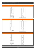
Page 20: ...APPENDIX 2 INSTALLATION EXAMPLES PAGE 21 1 2 3 4 MAX 1500 ...
Page 21: ...APPENDIX 2 INSTALLATION EXAMPLES PAGE 22 4 5 6 ...
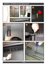
Page 22: ...APPENDIX 3 PREPARATION AND INSTALLATION PAGE 22 1 1 2 3 4 5 6 7 ...
Page 27: ...APPENDIX 6 ARRANGEMENT OF VARIOUS BURNER FILLINGS PAGE 29 PEBBLES 1 2 ...


