


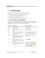


Troubleshooting
Checking Power Supply
VT400 Technical Manual, Rev. A5
62
Doc
#
UM-VT400-EN
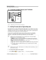
9.3 Checking Power Supply
If the unit does not turn on:
Check 24VDC power supply.
Check the resettable fuse F3 on PCB 801.
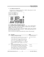
9.4 Checking Digital Input and Outputs
If the setpoints are not working properly, you can test them using the instructions
below.
To test digital input and outputs (setpoints):
1. Access the function menu and select function 93.
2. The display shows the status of the inputs and outputs, as follows:
The first digit from the left displays data received on the digital input
channel.
The fifth digit from the left displays data sent on output 1.
The sixth digit from the left displays data on output 2.
3. Press
(
) to toggle output 1 on and off. When it is on, the data sent should
be displayed in the fifth digit. If the output connects to another device, check if the
signal was received.
4.
Press
TOTAL
( ) to toggle output 2 on and off. When it is on, the data sent should
be displayed in the sixth digit. If the output connects to another device, check if
the signal was received.
5. Connect a device to the digital input, and send a signal. See if the data appears in
the first digit.


