
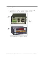


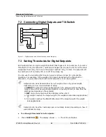


Outputs and Digital Input
Setting Thresholds for Digital Setpoints
VT400 Technical Manual, Rev. A5
51
Doc
#
UM-VT400-EN
2. Editing setpoints is function 01, so press
t
(
TARE
) to move to the second digit. It
starts flashing.
3. Press
u
(
P.TARE
) once. The display should now show
Fn 01
.
4.
Press
( ) to confirm. The display shows
SEtP 1
briefly. Then it shows the
current threshold for setpoint 1. The extreme-left digit flashes.
If you don’t want to change this threshold, press
( ) and skip to step
6.
If you do want to change it, proceed to the next step.
5. Enter a new threshold value. To do this, press
u
(
P.TARE
) to change the current
digit, then
t
(
TARE
) to move to the next digit. To finish, press
( ).
6. The display now shows
SEtP 2
briefly, then the current threshold for setpoint 2.
The extreme-left digit flashes.
If you don’t want to change this threshold, press
( ) and skip to step
8.
If you do want to change it, proceed to the next step.
7. Enter a new threshold value. To do this, press
u
(
P.TARE
) to change the current
digit, then
t
(
TARE
) to move to the next digit. When you are done, press
( ).
8. The threshold values are saved in EEPROM memory.
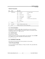
7.3.1
Parameters for Digital Outputs
The following parameters can be edited by accessing
SETUP
>
SETUP 5
.
Par.
Description
Values
5.1, 5.2
Setpoint 1 output
.
5.1=0 and 5.2=0: normal
5.1=1 and 5.2=0: no motion
5.1=0 and 5.2=1: error
5.3, 5.4
Setpoint 2 output
.
5.3=0 and 5.4=0: normal
5.3=1 and 5.4=0: zero
5.3=0 and 5.4=1: net
5.6
Net / gross
for both setpoints
. 0=net
1=gross
5.7
Normally open / closed for both setpoints
.
0=normally open
1=normally closed


