Virginia Controls, LLC
MH-3000 User Manual, 1_03C10-VC
Page 37
5.5.1.4
CPU Connectors
5.5.1.4.1
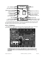
Duplex Communication Connector
The Duplex Communication Connector is a terminal
block located on the left side of the CPU board.
A shielded twisted pair is used to connect the two CPU
boards together. The shield is connected to the CPU
board mounting screw (which is grounded) at ONE END
OF THE CABLE ONLY. The termination jumpers next to
the connector are factory installed on duplex systems.
5.5.1.4.2
LCD Display Connector
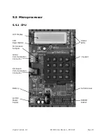
The LCD Display Connector is located at the top left of the CPU board.
The LCD display is mounted directly on the connector. The LCD display can be removed
for replacement. If it is removed, then set switch 1 on the Slide Switch S2 to the OFF
position before turning the power back on. This will ensure the CPU does not try to write to
the LCD screen while it is removed. It is recommended that the LCD display AND the
Keypad be removed together, since if the LCD display only is removed, and the keypad is
activated, the CPU will probably lock up. Make sure the power is turned OFF before
removing either the keypad or the LCD display.
5.5.1.4.3
Keypad Connector
The connector for the Keypad is located behind the keypad. The connector is an 8pin
connector. If the keypad is removed, make sure the connector is lined up properly when
replacing the keypad. Make sure the power is OFF when removing or installing the keypad.

