45
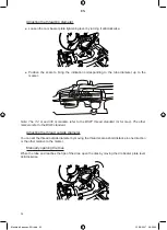
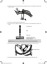
Put the jaw holding plate down, rear facing upwards, and unscrew the jaw holder helical drive
ring:
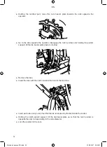
Turn the jaw holding plate over and remove the three jaw holders:
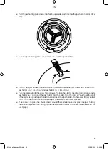
Put the new jaw holders into their correct numbered locations: jaw holder no. 1 in slot no.1,
jaw holder no. 2 in slot no.2 and jaw holder no. in slot no..
Turn the plate with its three jaw holders over. Position the start of the drive ring spiral opposite
jaw holder no.1 and insert the jaw holder into the spiral. Turn the ring 120° such that the start
of the spiral is opposite jaw holder no.2 and insert the jaw holder. Do the same for jaw holder
no.. Continue to turn the ring until the jaw holders are completely blocked.
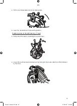
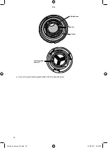
If necessary, replace the chuck crown around the spindle nose and place the jaw holding
plate on the spindle nose, lining up the nose pin with the slot on the disc (see figures on the
next page).
●
●
●
●
●
Machine 4 pouces-EN.indd 45
22/08/2007 08:59:58
EN
Summary of Contents for 162140
Page 3: ...Machine 4 pouces EN indd 2 22 08 2007 08 59 01 EN ...
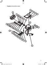
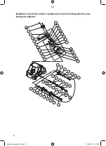
Page 55: ...53 Exploded view of the motor Machine 4 pouces EN indd 53 22 08 2007 09 00 02 EN ...
Page 57: ...55 Exploded view of the saddle Machine 4 pouces EN indd 55 22 08 2007 09 00 04 EN ...
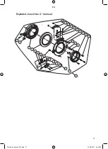
Page 59: ...57 Exploded view of the 4 die head Machine 4 pouces EN indd 57 22 08 2007 09 00 05 EN ...
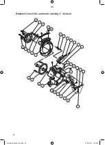
Page 61: ...59 Exploded view of the 1 4 3 8 die head Machine 4 pouces EN indd 59 22 08 2007 09 00 07 EN ...
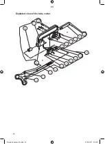
Page 62: ...60 Exploded view of the tube cutter Machine 4 pouces EN indd 60 22 08 2007 09 00 07 EN ...
Page 63: ...61 Exploded view of the reamer Machine 4 pouces EN indd 61 22 08 2007 09 00 07 EN ...
Page 64: ...62 Components of a nipple holder Machine 4 pouces EN indd 62 22 08 2007 09 00 08 EN ...
Page 65: ...EN ...
Page 66: ...EN ...
Page 67: ...EN ...


