28
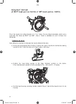
Using the 2” die head (Part no. 162151)
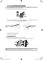
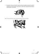
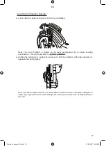
Installing the head
Note: When the machine is delivered, the dies are not mounted on the 2” head.
See page 35 for the procedure for installing dies for the 2” head.
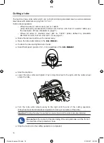
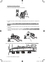
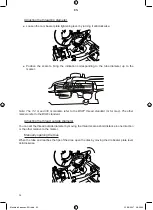
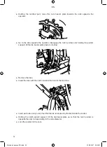
Tilt the die head support block to the left. (This block is located behind the locking lever for
the 4” head, the lever with “Open” plate on its body).
Position the head tilting spindle in the small diameter cylinder on the frame. (The large
diameter cylinder receives the spindle for the 4” head).
Tilt the head to lock it in the die head support block (see above).
●
●
●
Machine 4 pouces-EN.indd 28
22/08/2007 08:59:34
EN
Summary of Contents for 162140
Page 3: ...Machine 4 pouces EN indd 2 22 08 2007 08 59 01 EN ...
Page 55: ...53 Exploded view of the motor Machine 4 pouces EN indd 53 22 08 2007 09 00 02 EN ...
Page 57: ...55 Exploded view of the saddle Machine 4 pouces EN indd 55 22 08 2007 09 00 04 EN ...
Page 59: ...57 Exploded view of the 4 die head Machine 4 pouces EN indd 57 22 08 2007 09 00 05 EN ...
Page 61: ...59 Exploded view of the 1 4 3 8 die head Machine 4 pouces EN indd 59 22 08 2007 09 00 07 EN ...
Page 62: ...60 Exploded view of the tube cutter Machine 4 pouces EN indd 60 22 08 2007 09 00 07 EN ...
Page 63: ...61 Exploded view of the reamer Machine 4 pouces EN indd 61 22 08 2007 09 00 07 EN ...
Page 64: ...62 Components of a nipple holder Machine 4 pouces EN indd 62 22 08 2007 09 00 08 EN ...
Page 65: ...EN ...
Page 66: ...EN ...
Page 67: ...EN ...


