


Manual VIPA System SLIO
Chapter 3 Deployment
HB300E - IM - RE_053-1DN00 - Rev. 11/21
3-5
From VIPA you may receive an appropriate EDS file (
E
lectronic
D
ata
S
heet) for your DeviceNet coupler, which depends on your configuration
(number of modules).
These files may either be found on the supplied storage media or at the
download area of www.vipa.de. Please install the required EDS file in your
configuration tool. Details on the installation of the EDS file are available in
the manual supplied with your configuration tool.
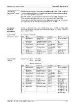
EDS file name
Usage
VIPA-053-1DN00_16-ext
VIPA-053-1DN00_32-ext
VIPA-053-1DN00_64-ext
Maximum number of diagnostics data (slow)
- supports maximally 16 System SLIO modules
- supports maximally 32 System SLIO modules
- supports maximally 64 System SLIO modules
VIPA-053-1DN00_16
VIPA-053-1DN00_32
VIPA-053-1DN00_64
Reduced Diagnose (fast)
(DeviceName, Parameter, Diagnostics)
- supports maximally 16 System SLIO modules
- supports maximally 32 System SLIO modules
- supports maximally 64 System SLIO modules
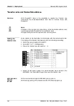
The DeviceNet coupler determines automatically the modules on the
System SLIO bus and generates from this the number of input and output
bytes. During the configuration of the DeviceNet scanner the
corresponding overall length of the input and the output bytes is to be
preset. Information concerning the I/O allocation of a module may be found
in the corresponding manual.
The position (offset) of the input respectively output bytes within the input
respectively output data results from the order of the modules (DeviceNet-
Slot 1 ... 64). By means of the base address, which is to be preset in the
DeviceNet scanner for the bus coupler and the offset you may access the
input or output data of a module.
During operation the DeviceNet coupler cyclically reads the input data of
the peripheral modules and serves for the last state of these data for the
DeviceNet scanner. Output data, which the DeviceNet coupler has received
from the DeviceNet scanner, were directly transferred to the modules, as
soon as they were received.
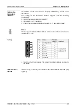
•
Turn off the power supply of the DeviceNet coupler and preset the
transfer rate and the DeviceNet address. More about this may be found
below at "Transfer rate and DeviceNet address".
•
Start the configuration tool of your DeviceNet scanner.
•
Set the DeviceNet scanner to connection type "POLL IO".
•
Enter the number of input and output data:
- Number input data: Produced connection size
- Number output data: Consumed connection size
•
Enter a base address for the input and output data (mapping).
•
Activate the System SLIO DeviceNet coupler IM 053DN in the scan list.
•
Start the DeviceNet scanner.
When the DeviceNet scanner has been configured, the input and output
modules are accessible via the configured addresses.
EDS file
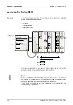
Accessing
I/O area
DeviceNet scanner
(master)
configuration
Summary of Contents for SLIO IM 053-1DN00
Page 1: ...VIPA System SLIO IM 053 1DN00 Manual HB300E_IM RE_053 1DN00 Rev 11 21 May 2011...
Page 4: ...Contents Manual VIPA System SLIO ii HB300E IM RE_053 1DN00 Rev 11 21...
Page 8: ...Safety information Manual VIPA System SLIO 4 HB300E IM RE_053 1DN00 Rev 11 21...
Page 28: ...Chapter 1 Basics and Assembly Manual VIPA System SLIO 1 20 HB300E IM RE_053 1DN00 Rev 11 21...


