VIPA SLIO IM 053-1DN00 Manual Download Page 26

Chapter 1   Basics and Assembly


Manual VIPA System SLIO 

1-18 


HB300E - IM - RE_053-1DN00 - Rev. 11/21 

Electrical, magnetically and electromagnetic interference fields are 
weakened by means of an isolation, one talks of absorption. 
Via the isolation rail, that is connected conductive with the rack, 
interference currents are shunt via cable isolation to the ground. Hereby 
you have to make sure, that the connection to the protected earth conduc-
tor is impedance-low, because otherwise the interference currents may 
appear as interference cause. 
 
When isolating cables you have to regard the following: 

• 

If possible, use only cables with isolation tangle. 

• 

The hiding power of the isolation should be higher than 80%. 

• 

Normally you should always lay the isolation of cables on both sides. 
Only by means of the both-sided connection of the isolation you achieve 
high quality interference suppression in the higher frequency area. 
Only as exception you may also lay the isolation one-sided. Then you 
only achieve the absorption of the lower frequencies. A one-sided 
isolation connection may be convenient, if: 
-  the conduction of a potential compensating line is not possible 
-  analog signals (some mV res. µA) are transferred 
-  foil isolations (static isolations) are used. 

• 

With data lines always use metallic or metalized plugs for serial 
couplings. Fix the isolation of the data line at the plug rack. Do not lay 
the isolation on the PIN 1 of the plug bar! 

• 

At stationary operation it is convenient to strip the insulated cable 
interruption free and lay it on the isolation/protected earth conductor line. 

• 

To fix the isolation tangles use cable clamps out of metal. The clamps 
must clasp the isolation extensively and have well contact. 

• 

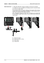
Lay the isolation on an isolation rail directly after the entry of the cable in 
the cabinet. Lead the isolation further on to the System SLIO module 
and 

don't 

lay it on there again! 


Please regard at installation! 

At potential differences between the grounding points, there may be a 
compensation current via the isolation connected at both sides. 
Remedy: Potential compensation line 


Isolation of 
conductors 


Summary of Contents for SLIO IM 053-1DN00

Page 1: ...VIPA System SLIO IM 053 1DN00 Manual HB300E_IM RE_053 1DN00 Rev 11 21 May 2011...

Page 2: ...c Compatibility Directive 2006 95 EC Low Voltage Directive Conformity is indicated by the CE marking affixed to the product Conformity Information For more information regarding CE marking and Declara...

Page 3: ...s 1 2 System conception 1 3 Dimensions 1 6 Installation 1 7 Wiring 1 11 Trouble shooting LEDs 1 15 Installation guidelines 1 16 General data 1 19 Chapter 2 Hardware description 2 1 Properties 2 2 Stru...

Page 4: ...Contents Manual VIPA System SLIO ii HB300E IM RE_053 1DN00 Rev 11 21...

Page 5: ...ere you will find the information required to assemble and wire a controller system consisting of System SLIO components Besides the dimensions the general technical data of System SLIO will be found...

Page 6: ...rs Every chapter provides a self contained description of a specific topic The following guides are available in the manual an overall table of contents at the beginning of the manual an overview of t...

Page 7: ...anual must be available to all personnel in the project design department installation department commissioning operation The following conditions must be met before using or commissioning the compone...

Page 8: ...Safety information Manual VIPA System SLIO 4 HB300E IM RE_053 1DN00 Rev 11 21...

Page 9: ...e information required to assemble and wire a controller system consisting of System SLIO components Besides the dimensions the general technical data of System SLIO will be found Topic Page Chapter 1...

Page 10: ...ge components thereby causing the module to become inoperable or unusable Modules that have been damaged by electrostatic discharges can fail after a temperature change mechanical shock or changes in...

Page 11: ...tronic power supply may be extended with 2A The System SLIO consists of the following components Bus coupler Periphery modules Power modules Accessories With a bus coupler bus interface and power modu...

Page 12: ...nic module which is mounted to the terminal module by a safe sliding mechanism With an error the defective module may be exchanged for a functional module with standing installation By an integrated c...

Page 13: ...ted underneath the terminal of the terminal module With a flat mounting rail for adaption to a flat mounting rail you may remove the spacer of the shield bus carrier With each bus coupler to protect t...

Page 14: ...Manual VIPA System SLIO 1 6 HB300E IM RE_053 1DN00 Rev 11 21 Dimensions 104 109 76 5 48 5 49 104 109 76 5 15 133 12 9 55 5 62 12 9 Dimensions in mm Dimensions bus coupler Dimensions periphery module...

Page 15: ...odule The module is fixed to the mounting rail by pushing downwards the locking lever The modules may either separately be mounted to the mounting rail or as block Here is to be considered that each l...

Page 16: ...with 2A More about this may be found at Wiring Mount the mounting rail Please consider that a clearance from the middle of the mounting rail of at least 80mm above and 60mm below respectively 80mm by...

Page 17: ...module you have to mount the bus cover now The shield bus carrier available as accessory serves to carry the shield bus to connect cable shields The shield bus carrier is mounted underneath the termin...

Page 18: ...ripes at both sides to the mounting rail 1 2 3 4 With mounting respectively de mounting of a module group you also have to remove the electronic module of the just mounted right module After mounting...

Page 19: ...vibration proof 10mm Umax 240V AC 30V DC Imax 10A Cross section 0 08 1 5mm2 AWG 28 16 Stripping length 10mm Wiring procedure 1 Insert a suited screwdriver at an angel into the square opening as shown...

Page 20: ...be externally protected with a fuse fast which corresponds to the maximum current This means max 10A is to be protected with a 10A fuse fast The electronic power supply for bus coupler and I O area i...

Page 21: ...a sum current of max 2A Afterwards the power module 007 1AB10 is to be placed again To secure the power supply the power modules may be mixed used 007 1AB00 Sys DC 5V DC 24V 10A 007 1AB00 Sys DC 5V D...

Page 22: ...s The shield bus carrier is mounted underneath the terminal of the terminal module With a flat mounting rail for adaption to a flat mounting rail you may remove the spacer of the shield bus carrier Af...

Page 23: ...place the power module 007 1AB10 More concerning this may be found above at Wiring RUN MF RUN MF RUN MF RUN MF RUN MF RUN MF RUN MF RUN MF RUN MF RUN MF Behavior After PowerON the MF LED of one module...

Page 24: ...nterferencing the environment All System SLIO components are developed for the deployment in industrial environments and fulfill high demands on the EMC Nevertheless you should project an EMC planning...

Page 25: ...g lines must be laid isolated When transmitting signals with small amplitudes the one sided laying of the isolation may be favorable Lay the line isolation extensively on an isolation protected earth...

Page 26: ...ation one sided Then you only achieve the absorption of the lower frequencies A one sided isolation connection may be convenient if the conduction of a potential compensating line is not possible anal...

Page 27: ...C Vertical installation EN 61131 2 0 60 C Air humidity EN 60068 2 30 RH1 without condensation rel humidity 10 95 Pollution EN 61131 2 Degree of pollution 2 Mechanical Oscillation EN 60068 2 6 1G Shock...

Page 28: ...Chapter 1 Basics and Assembly Manual VIPA System SLIO 1 20 HB300E IM RE_053 1DN00 Rev 11 21...

Page 29: ...11 21 2 1 Chapter 2 Hardware description Here the hardware components of the IM 053 1DN00 are more described You will find the technical data at the end of this chapter Topic Page Chapter 2 Hardware...

Page 30: ...ode support no CHANGE OF STATE support Profile Generic Device Configuration via DIP switch DeviceNet address 0 63 Attitude of the baud rate for DeviceNet slave supports all baud rates 125 250 and 500k...

Page 31: ...ctor LED Color Description PWR green Bus interface is power supplied SF red Error on DeviceNet or System SLIO bus RD green Status System SLIO bus MT yellow Status DeviceNet Status indication bus inter...

Page 32: ...ly 8 Sys 0V I GND for electronic section supply I Input The DeviceNet connection is provided by a 5pin open style connector The pin assignment is imprinted on the front of the module The shield is to...

Page 33: ...ormal operation are not recognized Transfer rate No Description Example setting 1 Configuration 1 2 Transfer rate 125kbit s 0 3 Transfer rate 250kbit s 1 4 Transfer rate 500kbit s 0 5 6 7 8 not used T...

Page 34: ...ation read out possible Supply voltage display green LED Group error display red SF LED Channel error display none Hardware config Racks max 1 Modules per rack max 64 Number of digital modules max 64...

Page 35: ...es the usage of the IM 053 1DN00 with DeviceNet After a short introduction you may find here every information for the usage in the System SLIO Topic Page Chapter 3 Deployment 3 1 Basics DeviceNet 3 2...

Page 36: ...type In contrast to the classical source destination model DeviceNet uses a modern producer consumer model that requires data packets with identifier fields for the identification of the data This ap...

Page 37: ...e Multiple Access CSMA principle i e every station on the network may access the bus when it is not occupied random access The exchange of messages is message orientated and not station orientated Eac...

Page 38: ...Bytes 10 Slot Output Slot Input 1 2 3 4 5 4 I O Mapping Parameterization DeviceNet Scanner Master DeviceNet Device Slave Configuration tool Param 1 2 3 4 5 4 Param Param Diag Diag Diag Diag Diag Diag...

Page 39: ...concerning the I O allocation of a module may be found in the corresponding manual The position offset of the input respectively output bytes within the input respectively output data results from th...

Page 40: ...ing Value as Range of values Character string Example Number x 1Byte hexadecimal 00h FFh xhh xA2 2x 2Byte hexadecimal 0000h FFFFh 2xhhhh 2x7FFF 4x 4Byte hexadecimal 00000000h FFFFFFFFh 4xhhhhhhhh 4x7F...

Page 41: ...rsion String 02 3 SwVersion Software version String V101 4 SerialNumber Serial number Unsigned32 String 00000205 5 FpgaVersion FPGA version Unsigned16 String V208 6 MxFile MX file String MX000053 101...

Page 42: ...ransfer rate The setting of the transfer rate happens with the following proceeding Switch the power supply to PowerOFF Set switch 1 to 1 Configuration Preset the transfer rate with switch 2 4 No Desc...

Page 43: ...dress with switch 2 7 as a binary value Note Please regard each DeviceNet address is taken once at the bus between a number of 0 63 No Value Example setting Address 1 Configuration 0 2 20 1 1 3 21 2 1...

Page 44: ...error Error in EDS file Transfer error Error in flash X X 0 Field bus is offline no DC 24V on the connector no further station on the field bus X X B Field bus ready no connection established X X 1 F...

Reviews: