


Chapter 2 Hardware description
Manual VIPA System SLIO
2-4
HB300E - IM - RE_053-1DN00 - Rev. 11/21
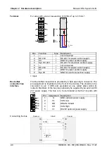
For wires with a core cross-section of 0.08mm
2
up to 1.5mm
2
.
2
6
3
7
4
8
1
5
1
2
3
4
5
6
7
8
2
6
3
7
4
8
1
5
PM
Sys
DC24V
0V
DC24V
0V
DC24V
0V
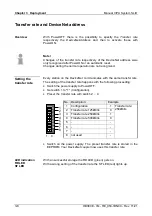
Pos.
Function
Type Description
1 ---
--- not
connected
2
DC 24V
I
DC 24V for power section supply
3
0V
I
GND for power section supply
4
Sys DC 24V
I
DC 24V for electronic section supply
5 ---
--- not
connected
6
DC 24V
I
DC 24V for power section supply
7
0V
I
GND for power section supply
8
Sys 0V
I
GND for electronic section supply
I: Input
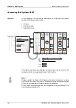
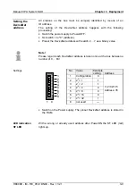
The DeviceNet connection is provided by a 5pin open style connector. The
pin assignment is imprinted on the front of the module. The shield is to be
connected to pin 3 (DR) and grounded at one suited place within its
network. Members of the bus may optionally be supplied by an external DC
24V power supply. The bus is to be terminated at both of its ends with
120
Ω
.
Pin Assignment Description
1
V-
GND optional power supply
2 CL
CAN
Low
3
DR
DRAIN / Shield
4 CH
CAN
High
5
V+
DC24V optional power supply
V-
CL
DR
CH
V+
Scanner
Coupler
CH
Shield
120
Ω
4
2
3
120
Ω
CL
DR
DR
24V
+
-
V-
V-
V+
V+
1
5
CL
CH
optional
Terminal
DeviceNet
connector bus
interface
Connecting the bus
Summary of Contents for SLIO IM 053-1DN00
Page 1: ...VIPA System SLIO IM 053 1DN00 Manual HB300E_IM RE_053 1DN00 Rev 11 21 May 2011...
Page 4: ...Contents Manual VIPA System SLIO ii HB300E IM RE_053 1DN00 Rev 11 21...
Page 8: ...Safety information Manual VIPA System SLIO 4 HB300E IM RE_053 1DN00 Rev 11 21...
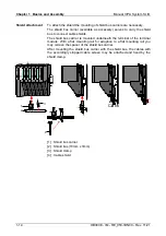
Page 28: ...Chapter 1 Basics and Assembly Manual VIPA System SLIO 1 20 HB300E IM RE_053 1DN00 Rev 11 21...


