


Manual VIPA Accessories
Chapter 4 Deployment
HB37E - IM - RE_306-1LE00 - Rev. 09/28
4-21
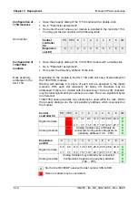
The interrupt section of the slave diagnostic shows information about
interrupt type and cause. It consists of max. 12bytes. For every slave
diagnostic max. 1 interrupt may be sent. The interrupt section is always the
last part of the diagnostic telegram if activated in the parameterization.
If there is a diagnostic event for a channel of a module, there may be a
module error as well as a channel error.
Interrupt status
Byte
Bit 7 ... Bit 0
x
Bit 5 ... 0: 010100: Length of the interrupt section incl. byte x
Bit 7 ... 6: 00 (fix) Code for module-related diagnostic
x+1
Bit 6 ... 0: Type of interrupt
0000001:
Diagnostic
interrupt
Bit 7: Code for interrupt
x+2
Bit 7 ... 0: Slot of the module that is producing interrupt
1
...
20
x+3
Bit 1,0:
00: reserved
01:
Diagnostic
interrupt
incoming
10:
Diagnostic
interrupt
outgoing
11:
reserved
Bit 2: 0 (fix)
Bit 7 ... 3: interrupt sequence number 1 …32
x+4
Bit 0: QVZ - acknowledgement delay: Module at rack has
malfunction respectively is missing
Bit 7 ... 1: reserved
x+5
Bit 3 ... 0: Module class
1111:
Digital
module
0101:
Analog
module
Bit 7 ... 4: reserved
x+6
70h: Module with digital inputs
71h: Module with analog inputs
72h: Module with digital outputs
73h: Module with analog outputs
x+7
Number of channels per module
x+8
High byte rack periphery address
x+9
Low byte rack periphery address
x+10
Diagnostic event for channel 7 ... 0
x+11
Diagnostic event for channel 15 ... 8
Interrupts
Interrupt status