


Chapter 4 Deployment
Manual VIPA Accessories
4-14
HB37E - IM - RE_306-1LE00 - Rev. 09/28
•
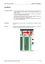
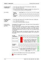
Open the property dialog of the 115U module with a double-click.
•
Go to "Parameter assignment".
•
Here enter the slot where your module is installed in the rack AG-115U.
You may get the slot number at the following table.
Central
controller
CC
PS CPU
0
1
2
3
4
5
6
IM
Expansion
unit EU
0
1
2
3
4
5
6
7
8
9
•
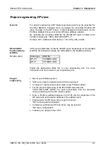
Open the property dialog of the 135U/155U module with a double-click.
•
Go to "Parameter assignment".
•
Here enter the
Periphery address
of the rack.
Depending on the module in the AG-115U each slot has a fixed address for
the 135U/155U modules.
Starting with address 0.0, 4byte of each slot are assigned to the digital
modules. With each slot maximally 32 binary I/O channels may be
addressed. If there is a module with 8 respectively 16 binary I/O channels,
only the least significant byte numbers are used. The more significant bytes
are irrelevant.
135U/155U analog modules may arbitrarily be used within the rack. Within
the property dialog enter the rack periphery address, which is selected on
the module.
Central
controller CC
PS CPU
0
1
2
3
4
5
6
IM
Digital modules
0.0
...
3.7
4.0
...
7.7
8.0
...
11.7
12.0
...
15.7
16.0
...
19.7
20.0
...
23.7
24.0
...
27.7
X
X
X
Analog modules
Analog modules may arbitrarily be
connected. Configuration happens via
periphery address (128 ... 255)
X
X
X
Expansion
unit EU
0
1
2
3
4
5
6
7
8
9
Digital modules
0.0
...
3.7
4.0
...
7.7
8.0
...
11.7
12.0
...
15.7
16.0
...
19.7
20.0
...
23.7
24.0
...
27.7
28.0
...
31.7
32.0
...
35.7
X
X
X
Analog modules
Analog modules may arbitrarily be connected.
Configuration happens via periphery address
(128 ... 255)
X
X
X
X : Slot for the IM 306 DP slave with order number 306-1LE00.
: Here no module may be connected.
Configuration of
115U modules
Slot number
Configuration of
135U/155U
modules
Rack
periphery
addresses
in the
AG-115U