


Chapter 4 Deployment
Manual VIPA Accessories
4-20
HB37E - IM - RE_306-1LE00 - Rev. 09/28
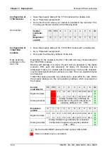
With the
Channel related diagnostic
you gain detailed information about the
channel error within a module. For the usage of the
Channel related
diagnostic
you have to release the diagnostic interrupt for every module via
the parameterization. The
Channel related diagnostic
may be activated via
the parameterization and has the following structure:
Channel related diagnostic for one channel
Byte
Bit 7 ... Bit 0
X
Bit 5 ... 0: ID number of the module that delivers the
Channel
specific
diagnostic
(000001 ... 010011)
e.g.: Slot 1 has ID no. 0
Slot 20 has ID no. 19
Bit 7, 6: 10 (fix) Code for channel-related diagnostic
X+1
Bit 5 ... 0: Number of the channel or the channel group that
delivers the diagnostic (00000 .... 11111)
Bit 7 ... 6: 01=Input Module
10=Output
Module
11=In-/Output
Module
X+2
Bit 4 ... 0:
Error messages to Profibus standard
00001:
Short
circuit
00010: Undervoltage (Supply voltage)
00011: Overvoltage (Supply voltage)
00100: Output Module is overloaded
00101: Temperature rise output Module
00110: Open circuit sensors or actors
00111: Upper limit violation
01000: Lower limit violation
01001: Error - Load voltage at the output
- Sensor supply
- Hardware error in the Module
Error messages - manufacturer-specific
10000: Rack periphery address not occupied
10001: Address overlapping in
Prm-Data
10010: QVZ - acknowledgement delay
Bit 7 ... 5: Channel type
001:
bit
010:
2bit
011:
4bit
100:
byte
101:
word
110:
2words
The maximum number of
Channel related diagnostic
is limited by the total
length of 127byte for diagnostic. By de-activating of other diagnostic ranges
you may release these areas for further
Channel related diagnostics
.
For each channel always 3byte are used.
Channel-related
Diagnostic