background image

VIP Vision Residential IP Intercom Installation Guide - v1.3 Issued April 2017

30

6. 

After 30 seconds, your Door Station will 
connect to the Access Point.

7. 

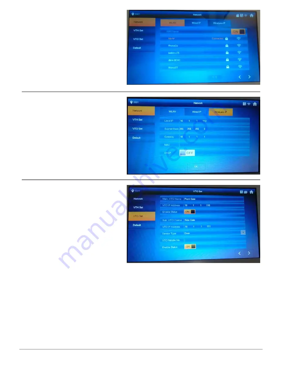
Select “Wireless IP” and set “DHCP” to 
“OFF”.

8. 

Change the IP address, subnet mask, 
and default gateway to match your local 
computer network. Press “OK” to save. 

In this example, we are going to change the IP 
address of the Indoor Monitor to 

10.1.1.112

the Subnet Mask to 

255.255.255.0

 and the 

Default Gateway to 

10.1.1.1

.

9. 

Select “VTO Set”. 

10. 

Change the IP address, of the Main VTO 
to the IP address that was set on the Door 
Station,  in this example the IP address is 

10.1.1.110

.

11. 

Change the “Main_VTO Name” and 


"Sub_VTO Name" to names of your 
choice, for example “Front Gate” and 
"Side Gate".

12. 

Change the IP address, of the Sub VTO 
to the IP address that was set on the 
second Door Station, in this example the 
IP address is 

10.1.1.111

.

13. 

Ensure “Enable Status” is set to “ON” for 
both the Main and Sub VTO.

Summary of Contents for INTIPMONDB

Page 1: ...VIP Vision Residential IP Intercom Installation Guide v1 3 Issued April 2017 1 VIP Residential IP Intercom Installation Guide INTIPMOND W B INTIPRDSDB INTIPRDSVW...

Page 2: ...4 2 6 2 Indoor Monitors to 2 Door Stations via a Wireless Access Point Wireless 26 2 6 1 Door Station 1 Configuration 27 2 6 2 Door Station 2 Configuration 28 2 6 3 Master Indoor Monitor Configuration...

Page 3: ...Door Station to a VIP Vision NVR 49 4 How to Use Your Intercom System 50 4 1 Making and Answering Calls 50 4 2 Taking Videos Snapshots from the Indoor Monitor 50 4 3 Viewing Your Videos Snapshots from...

Page 4: ...888888 which can be entered after holding the settings button for 6 seconds The Door Station s web interface will require the default username admin and password admin The Door Station s default IP ad...

Page 5: ...on Technology for High Quality Images 1024 x 600 pixel resolution 7 Touch Screen MicroSD Card Slot VIP Residential IP Intercom Door Station with WiFi Product ID INTIPRDSDB 1MP Camera Built in NFC Card...

Page 6: ...rn to the Indoor Monitor s homepage 6 Call button Accept call or hang up the current call 7 Unlock During a call or while monitoring a Door Station press to unlock that Door Station 1 Reset button Res...

Page 7: ...pressed down once installed If the switch is released the alarm will sound 3 Reset button Resets the Door Station 4 RJ 45 port Connect a Cat5 cable with the included adaptor 5 Input connectors Connect...

Page 8: ...er Switch This must be fully pressed down once installed If the switch is released the alarm will sound 3 RJ 45 Port Connect a Cat5 cable with the included adaptor 4 Debug Port Unused 5 Input Connecto...

Page 9: ...ust be provided to each Door Station and Indoor Monitor When connecting to the Door Stations web interface the default IP address is 192 168 1 110 We recommend using Internet Explorer to connect to th...

Page 10: ...uired for this installation 12VDC power for both the Door Station and Indoor Monitor Cat5 cables to connect between the Indoor Monitor Door Station and Network Switch sold separately and between the N...

Page 11: ...Network Settings 888888 by default 2 Select Wired IP and change the IP address subnet mask and default gateway to match your local computer network Press OK to save In this example we are going to cha...

Page 12: ...to configure the Door Station A Windows computer for configuration In this example we are going to connect the Door Station and Indoor Monitor to a Wireless Access Point and assign static IP addresse...

Page 13: ...n select OK 7 After 30 seconds your Door Station will connect to the Access Point 8 Select System Config Network Config Under Eth2 set DHCP to Off 9 Select the default interface as Eth2 After this con...

Page 14: ...rk Settings 888888 by default 2 Select Wireless IP set DHCP to On and confirm with OK 3 Select WLAN and set it to ON 4 Select the Access Point you wish to connect to In this example we are going to co...

Page 15: ...1 110 7 Select Wireless IP and turn DHCP to OFF 8 Change the IP address subnet mask and default gateway to match your local computer network Press OK to save In this example we are going to change the...

Page 16: ...nitors and Door Station together though a wireless access point and provide them with network access The following is required for this installation 12VDC power for both the Door Station and the Indoo...

Page 17: ...n select OK 7 After 30 seconds your Door Station will connect to the Access Point 8 Select System Config Network Config Under Eth2 set DHCP to Off 9 Select the default interface as Eth2 After this con...

Page 18: ...this example we are going to connect to MyAP 5 When prompted enter the password for the Access Point then select OK This monitor will be configured as a Master Indoor Monitor 1 On the Master Indoor Mo...

Page 19: ...10 1 1 1 9 Select VTO Set Change the Main_VTO Name toanameofyourchoice forexample Front Gate 10 Change the IP address of the Main VTO to the IP address that was set on the Door Station in this example...

Page 20: ...ess subnet mask and default gateway to match your local computer network Press OK to save In this example we are going to change the IP address of the Indoor Monitor to 10 1 1 112 the Subnet Mask to 2...

Page 21: ...Issued April 2017 21 11 Select VTO Set Ensure Enable Status is set to ON for the Main_VTO 12 Turn off power to each Door Station and Indoor Monitor after 10 seconds turn the power back on You have no...

Page 22: ...s configuration allows you to connect your Indoor Monitor and Door Station together and provide them with network access The following is required for this installation 12VDC power for both the Door S...

Page 23: ...ion 1 2 for how to log in 2 Navigate to System Config Network Config 3 Under Eth0 change the IP address subnet mask and default gateway to match your local computer network Press OK to save In this ex...

Page 24: ...this example we are going to change the IP address of the Indoor Monitor to 10 1 1 113 the Subnet Mask to 255 255 255 0 and the Default Gateway to 10 1 1 1 This monitor will be configured as a Extens...

Page 25: ...ed April 2017 25 5 Select VTO Set Ensure Enable Status is set to ON for both the Main and Sub VTO 6 Turn off power to each Door Station and Indoor Monitor after 10 seconds turn the power back on You h...

Page 26: ...connect your Indoor Monitors and Door Stations together through a wireless access point and provide them with network access The following is required for this installation 12VDC power for both the D...

Page 27: ...prompted enter the password for the Access Point then select OK 7 After 30 seconds your Door Station will connect to the Access Point 8 Select System Config Network Config Under Eth2 set DHCP to Off...

Page 28: ...6 When prompted enter the password for the Access Point then select OK 7 After 30 seconds your Door Station will connect to the Access Point 8 Select System Config Network Config Under Eth2 set DHCP...

Page 29: ...and 6902 for the second Door Station 2 Select WLAN then select ON 3 Select Wireless IP and set DHCP to ON then select OK 4 Select WLAN then select the Access Point you wish to connect to In this examp...

Page 30: ...e Indoor Monitor to 10 1 1 112 the Subnet Mask to 255 255 255 0 and the Default Gateway to 10 1 1 1 9 Select VTO Set 10 Change the IP address of the Main VTO totheIPaddressthatwassetontheDoor Station...

Page 31: ...example we are going to connect to MyAP 5 When prompted enter the password for the Access Point then select OK 6 After 30 seconds your Door Station will connect to the Access Point This monitor will b...

Page 32: ...and the Default Gateway to 10 1 1 1 11 Select VTO Set Ensure Enable Status is set to ON for both the Main and Sub VTO 12 Turn off power to each Door Station and Indoor Monitor after 10 seconds turn t...

Page 33: ...allows you to connect your Indoor Monitors and Door Stations together through a network switch and provide them with network access The following is required for this installation 12VDC power for bot...

Page 34: ...then log in to the Door Station sWeb Interface Refer to Section 1 2 for how to log in 2 Navigate to System Config Network Config 3 Under Eth0 change the IP address subnet mask and default gateway to...

Page 35: ...mple the IP address is 10 1 1 111 6 Ensure Enable Status is set to ON for both the Main and Sub VTO 2 Select Wired IP and change the IP address subnet mask and default gateway to match your local comp...

Page 36: ...th the Door Station and Indoor Monitor after 10 seconds turn the power back on 7 You have now successfully connected your VIP Residential IP Intercom This monitor will be configured as a Extension Ind...

Page 37: ...on for 6 seconds then enter the password for the Network Settings 888888 by default 3 Select VTH Set if wish to change the Wired Interface IP address select Wired IP If you wish to change the Wireless...

Page 38: ...w time and date 3 3 Setting the Time and Date 1 Log in to the Door Station s Web Interface Refer to Section 1 2 for how to log in 2 Once logged in go to System Config Local Config System Time In this...

Page 39: ...trols the microphone volume level VTO Beep Volume Controls the speaker sounds such as Door unlocked please enter 1 Log in to the Door Station s Web Interface Refer to Section 1 2 for how to log in 2 O...

Page 40: ...egative is connected to the Door Stations NO or NC terminal depending on the model of door strike 3 7 Wiring an Electric Door Strike to the Door Station Normally Closed Door Strike Wiring Normally Ope...

Page 41: ...Part No ACKEY103 3 9 Learning in Swipe Cards 1 Log in to the Door Station s Web Interface Refer to Section 1 2 for how to log in 2 You will then be able to go to System Config Local Config A C Manager...

Page 42: ...rn the Unlock option to OFF If a user has lost an NFC swipe card it can be deleted by logging in to the Web Interface of the Door Station The Indoor Monitor can trigger the Door Stations built in rela...

Page 43: ...ave more than one Door Station and wish to remotely access each one this procedure must be done on each Door Station 3 12 P2P Configuration QR Code 1 Log in to the Door Station s Web Interface Refer t...

Page 44: ...own reference and enter the username and password for the Door Station The username is admin and the password is also admin by default 12 Select the picture of the QR Code on the mobile application a...

Page 45: ...Intercom is and wish to connect via the internet or 3G 4G you would use the External static IP address given to you by your Internet Service Provider Port forwarding support There are many different...

Page 46: ...and press the Enter key If you wish to connect your IP intercom to the network for remote access you must give each Indoor Monitor and Door Station an IP address within your network range In this exam...

Page 47: ...run a PoE Network switch to a PoE Receiver Part No WT CAT5POER The receiver then splits the power and data which you can connect to the Door Station One PoE receiver is required for each device you wi...

Page 48: ...r go to Monitor IPC and select the Add button 2 In this menu you can enter a name for the IP Camera IP address username and password 3 Once you have entered in the details of the cameras you wish to a...

Page 49: ...e on the same IP address range Adding a Door Station to your NVR system will take up a single channel for each Door Station The Door Station will be recording constantly it is not able to be set for m...

Page 50: ...can automatically capture snapshots to the Micro SD Card when someone rings the Door Station and no one answers the call On the Indoor Monitor press the Settings button then enter the password 123456...

Page 51: ...later To play videos that have been recorded the Smart Player software needs to be installed on the computer 4 4 Viewing Your Videos Snapshots from a Computer If you have more than one Indoor Monitor...

Page 52: ...of dialing the room number each time you wish to make a call 1 On the Indoor Monitor go to Call Contact 4 5 Create Favourites 2 Select the Add button Enter in a name for the room and the room number...

Page 53: ...he Config Tool from the Support page on the VIP Vision website www vip vision com 2 Once the software has been downloaded to your computer extract the files and open Configtool exe 3 Once the software...

Page 54: ...the upgrade Please wait while the firmware is being updated do not close the Config Tool or unplug the computer or Door Station from the network as this may cause damage to your device 7 Once the upg...

Page 55: ...Wi Fi Network Press and hold the Reset button for 30 seconds to reset the Door Station to default settings Door Station and Indoor Monitors not connecting Reboot All Devices and Wait 5 minutes to ensu...

Page 56: ...er warranty express or implied or upon any other basis of liability whatsoever even the loss or damage is caused by its own negligence or fault Seller does not represent that the products it sells may...

Reviews: