background image

22

Indice

•  Regole d’installazione  .....................................................................  2

      Direttive   ..........................................................................................  2

• Descrizione 

 .....................................................................................  3

•  Caratteristiche tecniche  ...................................................................  3

Unità elettronica con telecamera  .....................................................  3

Morsettiera  ......................................................................................  4

•  Operazioni preliminari  .....................................................................  4

•  Attribuzione del codice identificativo ID 

 ...........................................  5

Procedura di configurazione ID delle unità elettroniche 

 ..................  5

•  Configurazione dei parametri 

 ..........................................................  6

Parametri  .........................................................................................  7

Procedura di configurazione dei parametri dell’unita’ elettronica

attraverso la tastiera italiano ............................................................  8

Procedura di configurazione dei parametri dell’unita’ elettronica

attraverso la tastiera inglese ............................................................ 10

•  Schemi di collegamento  .................................................................. 12

REGOLE D’INSTALLAZIONE

L’installazione deve essere effettuata con l’osservanza delle disposizioni 

regolanti l’installazione del materiale elettrico in vigore nel paese dove i 

prodotti sono installati.

CONFORMITÀ NORMATIVA.

Direttiva EMC.
Norme EN 61000-6-1, EN 61000-6-3.

INFORMAZIONE AGLI UTENTI AI SENSI DELLA DIRETTIVA 2002/96 

(RAEE)

Al fine di evitare danni all’ambiente e alla salute umana oltre che 

di incorrere in sanzioni amministrative, l’apparecchiatura che riporta 

questo simbolo dovrà essere smaltita separatamente dai rifiuti ur

-

bani ovvero riconsegnata al distributore all’atto dell’acquisto di una 

nuova. La raccolta dell’apparecchiatura contrassegnata con il simbolo del 

bidone barrato dovrà avvenire in conformità alle istruzioni emanate dagli 

enti territorialmente preposti allo smaltimento dei rifiuti. Per maggiori infor

-

mazioni contattare il numero verde 800-862307.

Contents

•  Installation rules

 ...............................................................................  2

      Directives   ........................................................................................  2

• Description 

 ......................................................................................  3

•  Technical specifications 

 ...................................................................  3

Electronic unit with camera  .............................................................  3

Terminal  

 ..........................................................................................  4

•  Preliminary procedures  ...................................................................  4

•  ID code assignment 

 ........................................................................  5

ID configuration procedure for the electronic units 

..........................  5

•  Parameter configuration 

 ..................................................................  6

Parameters  ......................................................................................  7

Electronic unit parameter configuration procedure using the 

keyboard italian ................................................................................  8

Electronic unit parameter configuration procedure using the 

keyboard .......................................................................................... 10

•  Wiring diagrams  .............................................................................. 12

INSTALLATION RULES

Installation should be carried out observing current installation regulations 

for electrical systems in the country where the products are installed.

CONFORMITY

EMC directive
Standards EN 61000-6-1, EN 61000-6-3.

USER INFORMATION IN COMPLIANCE WITH EUROPEAN

DIRECTIVE 2002/96 (RAEE).

In order to avoid damage to the environment and human health as 

well as any administrative sanctions, any appliance marked with this 

symbol must be disposed of separately from municipal waste, that 

is it must be reconsigned to the dealer upon purchase of a new 

one. Appliances marked with the crossed out wheelie bin symbol must be 

collected in accordance with the instructions issued by the local authorities 

responsible for waste disposal. 

Summary of Contents for Elvox 13F3

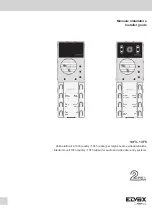
Page 1: ...audio 13F5 video per targhe audio e videocitofoniche Electronic unit 13F3 audio 13F5 video for audio and video door entry systems 3 2 1 4 START SI YES 5 STOP NO 6 FINE END 1 PREC PREV 2 SUCC NEXT 3 OK 3 2 1 4 START SI YES 5 STOP NO 6 FINE END 1 PREC PREV 2 SUCC NEXT 3 OK ...

Page 2: ...ta con il simbolo del bidone barrato dovrà avvenire in conformità alle istruzioni emanate dagli enti territorialmente preposti allo smaltimento dei rifiuti Per maggiori infor mazioni contattare il numero verde 800 862307 Contents Installation rules 2 Directives 2 Description 3 Technical specifications 3 Electronic unit with camera 3 Terminal 4 Preliminary procedures 4 ID code assignment 5 ID confi...

Page 3: ... SR F2 F1 M X CN2 CN1 CS2411 250105 4 START SI YES 5 STOP NO 6 FINE END 1 PREC PREV 2 SUCC NEXT 3 OK Cablaggio per collegamento morsettiera Cablaggio per collegamento moduli supplementari Regolazioni 1 Bilanciamento 2 Volume esterno 3 Volume interno Regolazione manuale orizzontale e verticale obiettivo Tasto programmazione Reset Electronic unit with camera Manual horizontal and vertical lens adjus...

Page 4: ...Ingresso video anima coassiale per telecamera esterna solo con 13F3 M Ingresso video calza coassiale per telecamera esterna solo con 13F3 PA Ingresso per sensore porta aperta con riferimento al morsetto M CA Comando apriporta con riferimento al morsetto M M Massa S Uscita serratura 12Vcc vedi nota sotto S Uscita serratura 12Vcc vedi nota sotto 12V Uscita 12V max 120 mA con limitatore di cor rente ...

Page 5: ...nd if the password is correct the entrance panel emits a sharp tone of confirmation otherwise it emits a low tone and exits the program ming phase Within 25 s press one of the buttons to assign the identification code to the SLAVE panel On the electronic unit configured as 13F3 13F5 and 12F3 12F5 the button at top right corresponds to the entrance panel SLAVE ID 2 the button indicated with 1 PREC ...

Page 6: ...o exited due to a timeout 30 s indicated by the emission of a low tone The timeout period is extended by 30 s every time a button is pressed For rapid exit from the programming phases press the END button at any time Procedura di assegnazione automatica identificativo ID secondario posti interni 7 Procedere come indicato nei punti 1 e 2 pag 5 8 Entro 5 minuti circa deve essere iniziata la procedur...

Page 7: ...ita ricerca targhe SLAVE SI disattivato Disabilitazioni autoaccensione No Sequenza autoaccensione Nessuna associazione Parameters The standard configuration can be changed using the buttons on the electronic unit standard configuration or the programmable time switch art 950C or the interface art 692I U connected to a PC on which the Sa veProg or EVCom software has been installed for the advanced ...

Page 8: ...di segnalazione ATTENDERE OCCUPATO inizieranno a lampeggiare per 8 volte e la targa emetterà un tono alto e continuo Durante il lam peggio premere in sequenza i tasti PREC OK STOP per avviare la cancellazione dell EEPROM Durante la cancellazione i LED rossi lampeggeranno velocemente Terminata la fase di reset l unita elettronica uscirà dalla programmazione e inizializ zerà il microprocessore Tasti...

Page 9: ...olamente quando la targa è nello stato di chiamata conversazione o di autoaccensione Valo re di default blocco disattivato Da modifica parametro premere il tasto START SI YES per abilitare o STOP NO per disabilitare la funzione Premere il tasto FINE per proseguire CICLI SUONERIA Definisce il numero di ripetizioni della suoneria del posto interno quando parte una chiamata dall unità elettronica Val...

Page 10: ...CK TIME OK FINE END F1 TIME EEPROM RESET Lists the default parameter values In parameter modification mode the WAIT BUSY indicator LEDs will start to flash 8 times and the entrance panel will emit a continuous high tone During flashing press the PREV OK and STOP buttons in sequence to start deletion of the EEPROM During deletion the red LEDs flash quickly When the reset phase is complete the elect...

Page 11: ...ess the END button to continue ENTRANCE PANEL LOCK BLOCK Activation of the lock block enables control of the lock only when the entrance panel is in call conversation or self start status Default value block disabled In parameter modification mode press the START SI YES button to enable or STOP NO to disable the function Press the END button to continue CHIME CYCLES Establishes the number of inter...

Page 12: ... video Audio or video electronic unit F Alimentatore di sistema System power supply unit L Serratura elettrica 12 Vdc Electric lock 12 Vdc P Comando apriporta Door release control X Cavo twistato Twisted cable Schema di collegamento di più unità elettroniche audio Wiring diagram for several audio electronic units SI693 Montante Cable riser P C P L L C P L X X X X C C Unità elettroniche audio Audio...

Page 13: ...o twistato Twisted cable G Alimentatore supplementare alimentazione unità elettronica Additional power supply for electronic unit J Concentratore Concentrator Schema di collegamento di unità elettronica audio singola con TLC tipo TVCC esterna Wiring diagram for single audio electronic unit with CCTV type external camera SI694 C Unità elettronica audio Audio electronic unit F Alimentatore di sistem...

Page 14: ...nti Additional electronic unit w 8 buttons 693P Modulo di espansione per 8 pulsanti Expansion module for 8 push buttons 1 2 EXT EXT M PA X VLED B1 B2 S S F2 F1 SR L 12V M M CA 12TS 12TD fino a 5 moduli 12TS o 12TD up to 5 12TS or 12TD modules fino a 24 moduli 693P up to 24 693P modules 1 2 3 4 5 OK R ITALY CN1 CN2 8 16 32 64 128 Art 693P ON CN2 CN1 CN2 CN1 CN2 CN1 CN2 CN1 CN2 CN1 1 2 3 4 5 OK R IT...

Page 15: ...te Version SI659 Unità elettronica a tasti e modulo con cartello numero civico retroilluminato Electronic unit with buttons and module with backlit house number plate Montante Cable riser Variante Version SI695 Collegamento per segnalazione Porta Cancello aperto Wiring for Door Gate open indication CA M M 12V L SR F1 F2 S S B2 B1 VLED X PA M EXT EXT 2 1 P2 P2 Sensore porta aperta N A a porta chius...

Page 16: ...Vimar SpA Viale Vicenza 14 36063 Marostica VI Italy Tel 39 0424 488 600 Fax Italia 0424 488 188 Fax Export 0424 488 709 www vimar com 49400631A0 MIITEN 03 16 02 VIMAR Marostica Italy ...

Reviews: