7/44
NT-50907601-KUBAIR-F400-ECOWATT-AN-191025
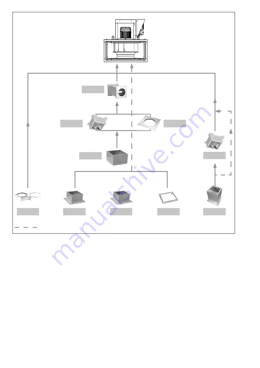
KUBAIR
®
F400 ECOWATT
MV
with vertical axis motor
TCDZ01
TCDZ05*
TCDZ03
SIL
TCDZ 04
TCDZ 07
TCDZ 02
TCDZ 09
ou
Optional accessory according to selection.
TCDZ08
Page 1: ...ATT AN 191025 TECHNICAL MANUAL INSTALLATION CONNECTION COMMISSIONING MAINTENANCE AFNOR CERTIFICATION ISO 14001 Environnement AFNOR CERTIFICATION ISO 9001 Q u a l i t KUBAIR F400 ECOWATT Smoke extract...
Page 2: ...recautions 14 5 2 Controllers 15 5 3 Operation for smoke extraction 20 5 4 Ventilation fault indication 20 5 5 KUBAIR F400 ECOWATT Single phase VAV variable flow rate control 20 5 6 KUBAIR F400 ECOWAT...
Page 3: ...ax 95 non condensing Atmosphere not potentially explosive Low salinity atmosphere with no corrosive chemical agents 1 2 Safety instructions Wear suitable PPE Personal Protective Equipment before any i...
Page 4: ...according to European Standard NF EN 12101 3 Approved F400 120 400 C 120 min KUBAIR F400 ECOWATT CC complete unit with multi directio nal suction plenum with horizontal or vertical axis motor KUBAIR...
Page 5: ...must not be fitted with motor down Size A BH BV BVC C D E EC F G GC H J K KC L Weight MV Kg Weight CC Kg Naked Insulated Naked Insulated 355 627 695 327 645 263 559 606 790 660 31 50 315 102 826 1103...
Page 6: ...UBZ 02 MSCZ MSDZ KUBZ 12 KUBZ 12 KUBZ 01 KUBZ 04 KUBZ 12 KUBZ 07 KUBAIR F400 ECOWATT MV KUBZ 03 KUBZ 12 KUBZ 08 KUBZ 01 KUBZ 12 KUBZ 07 KUBZ 03 The TCDZ accessories on the diagram below can be used wi...
Page 7: ...07601 KUBAIR F400 ECOWATT AN 191025 KUBAIR F400 ECOWATT MV with vertical axis motor TCDZ01 TCDZ05 TCDZ03 TCDZ03 SIL TCDZ 04 TCDZ 07 TCDZ 02 TCDZ 09 ou ou ou ou ou Optional accessory according to selec...
Page 8: ...necting flange is attached to the plain flange at its 4 corners for the purpose of attaching a sheath A A F Circular connection to the MV suction horizontal axis motor This connection is used with the...
Page 9: ...A B A B 355 658 391 658 636 400 731 425 731 721 450 812 453 812 790 500 890 485 890 828 630 1098 550 1098 953 710 1226 610 1226 1112 KUBZ 11 Model A B C D E Weight 355 622 448 238 355 662 21 400 694...
Page 10: ...ands under the casing It is incompatible with the use of the TCDZ 05 adapter plates and the TCDZ 01 standard support Make sure that the components are able to move freely before the casing is assemble...
Page 11: ...eight Kg Weight Kg D Weight Kg Weight Kg 355 400 2 5 5 0 315 355 400 450 1 8 1 5 1 2 0 8 23 0 450 500 4 0 6 0 400 450 500 560 3 6 3 1 2 5 1 7 37 0 630 4 5 8 0 450 500 560 630 5 1 4 5 3 7 2 7 45 0 710...
Page 12: ...between the support surface and the base of the casing A maximum incline of 2 5 is tolerated between the motor axis and the vertical axis see diagram below Let available space for maintenance operatio...
Page 13: ...oximity switch of the casing For the purpose of comfort the motor must be protected by an adapted magnetothermal protection mechanism This electronic commutation motor cannot be directly supplied by t...
Page 14: ...to each speed in the direction indi cated by the arrow on the product A centrifugal backward fan unit with an impeller that does not rotate in the right direction still creates a flowrate and a low pr...
Page 15: ...ts on the controller Connection of the relay For sizes 355 400 450 Controller Terminals 4 5 6 For sizes 500 630 710 Controller Terminals 17 18 19 Regardless of the principle of operation of the roof f...
Page 16: ...urrent regulator enabled 27 Over modulation regulation 0 1 Over modulation reached The converter can no longer provide the voltage required for the motor 28 Regeneration regulation 0 1 Motor in regene...
Page 17: ...col used is ModBus RTU 485 It is imperative to respect the rules of the art of a ModBus network for reliable communication You can connect up to 32 controllers on the same segment We recommend using t...
Page 18: ...22 23 Compacto 3 Convertisseur USB RS485 Terminaison 120 1 nF RX TX RX TX Segment D rivation A1 B1 A2 B2 A1 B1 A2 B2 A1 B1 A2 B2 Convertisseur USB RS485 RX TX RX TX 5 6 7 8 Invento 01 5 6 7 8 Invento...
Page 19: ...485 is necessary for you to connect to the registers via a PC as well as an interface of the same type as ModBus Doctor Single phase model 3 phase model MODBUS address 1 80 Baut rate 19200 START Bit 1...
Page 20: ...ormal Alimentation Ventilation defect indi cator light Running indicator light Power supply 5 5 KUBAIR F400 ECOWATT Single phase VAV variable flow rate control VAV Slaving to an external signal In var...
Page 21: ...Local control 5 5 1 Connection VAV type factory assembly and wiring with or without display Connection of the power supply to the INTZ switch to be done by the customer 1 2 3 4 5 6 7 8 9 10 11 12 13...
Page 22: ...an external signal When the speed adjustment is done by the CVF type remote control the 0 10V output or the Modbus BMS the factory fitted potentiometer in the controller must be disconnected CVF ON O...
Page 23: ...plied BCCA 2V 18 19 24V Start Stop Contr leur Noir Bleu Rouge P 0 PV GV 11 22 31 44 12 21 32 43 5V GND Pot 9 10 8 Controller Black Blue Red LS HS S 0 LS HS installation diagram with adjustable LS and...
Page 24: ...in bold in the table below The potentiometer in the controller allows you to change the speed of the turbine to adjust the flow rate The adjustment can be done with a CVF type remote control Correspon...
Page 25: ...mbers Value to be entered 1 Access to Level 1 5 1 2 Change in the operating mode of the controller 6 2 3 Saving of changes 5 10000 4 Changing the set point 0 Between 1000 and 10 000 to set the desired...
Page 26: ...the controller must be disconnected When the speed set point setting is given by the MODBUS BMS the factory fitted potentiometer in the controller must be disconnected as well as the shunt between ter...
Page 27: ...by a Modbus BMS set point To find the settings of the Modbus con nection refer to 5 2 4 Modbus connection Connection to a BMS After you wired your Modbus link Turn on the power to connect yourself to...
Page 28: ...actory assembly and wiring Connection of the power supply to the INTZ switch to be done by the customer 1 2 3 4 5 6 7 8 9 10 11 12 13 14 15 16 17 18 19 20 21 22 23 24 25 26 27 M Green Yellow U V W 24V...
Page 29: ...tion For a BMS controlling is only done by the 0 10V signal and GND Gas actuator output contact BDRA 16 17 Fire 24V Thermo switch N F 11 22 33 12 21 34 Factory fitted and wired 5 7 2 Adjusting the pre...
Page 30: ...t 16 Pressure Pa 100 100 100 160 200 300 200 320 300 500 300 480 400 700 400 640 450 800 500 800 450 1000 800 600 960 700 1 120 800 1 280 900 1 440 1000 1 600 5 8 KUBAIR F400 ECOWATT 3 phases VAV vari...
Page 31: ...temperature sensor VAV with regulation according to the deviation between the set point external measurement M Ventilateur Extraction TED F400 ECOWATT T Extract roof fan M Ventilateur Extraction TED F...
Page 32: ...V W Black Blue Red P ROOF FAN 1 234 SW1 1 2 3 Off On On TDPD Display Only on TED with display types L3 Brown Black Green Yellow Brown Grey INTZ 22A CASING TDPD Display only on KUBAIR with display typ...
Page 33: ...temperature sensor humidity sensor No 24V power supply if BMS connection For a BMS controlling is only done by the 0 10V signal and GND 0 10V OUTPUT 0 10V output Controller 9 10 GND An1 14 24V 12VDC M...
Page 34: ...only done by the 0 10V signal and GND 9 10 11 10V GND An1 3 4 0 10V Output Controller 12VDC Maxi Output signal GND Sensor power supply 24Vdc 40mA Maxi 0 10V OUTPUT 12 13 14 An2 GND 24V 15 16 Speed Out...
Page 35: ...o be entered 1 Access to Level 1 8 1 2 Change in the operating mode of the controller 10 2 3 Enabling of the on off in Modbus 13 1 4 Saving of changes 8 10000 5 Changing the set point 0 Between 0 and...
Page 36: ...factory fit ted potentiometer in the controller must be disconnected When the speed set point is given by the MODBUS BMS the factory fitted potentiometer in the controller must be disconnected as well...
Page 37: ...en by a Modbus BMS set point For the Modbus connection settings refer to 5 2 4 Modbus connection Connection to a BMS After you have wired your Modbus link Turn on the power to connect yourself to the...
Page 38: ...ion remote con trol by an external 0 10V output or by Modbus BMS 5 10 1 Wiring COP type factory assembly and wiring with or without display Connection of the power supply to the INTZ switch to be done...
Page 39: ...potentiometer in the controller must be disconnected When the speed set point is given by the MODBUS BMS the factory fitted potentiometer in the controller must be disconnected as well as the shunt be...
Page 40: ...a 8 8 800 Pa 1 280 Pa 9 9 800 Pa 1 440 Pa 10 10 800 Pa 1 600 Pa If the roof fan has a display the display will show you the pressure measured at the roof fan plate see diagram below Pressure measureme...
Page 41: ...0 1 600 6 MAINTENANCE The maintenance frequency depends on the operating conditions If the air is highly loaded with impurities the duration between two visits must be shortened WARNING Before any mai...
Page 42: ...BAIR F400 ECOWATT 355 Mono 230V 646890 MTTE KUBAIR ECOWATT 355 Mono 230V Spare motor fan KUBAIR F400 ECOWATT 400 Mono 230V 646891 MTTE KUBAIR ECOWATT 400 Mono 230V Spare motor fan KUBAIR F400 ECOWATT...
Page 43: ...ooden boxes and other non dangerous wastes must be made reusable by an approved service provider It is strictly prohibited to burn bury or dump them in nature 7 2 Treatment of a Professional WEEE This...
Page 44: ...antly concerned about improving his equipment the manufacturer re serves the right to make all technical changes without notice VIM Les pr s de M gy Sud SOUDAN CS 60120 79401 ST MAIXENT L ECOLE CEDEX...