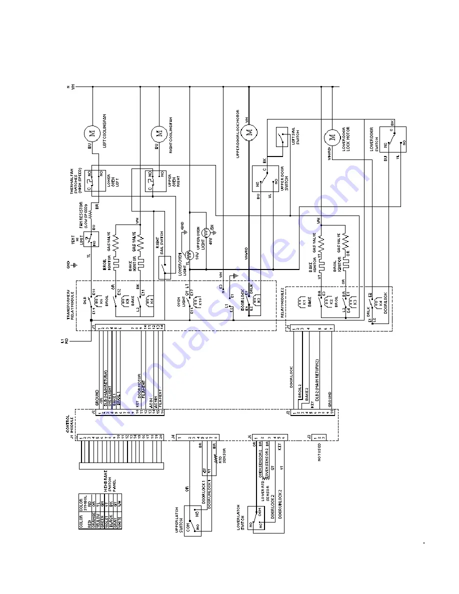
SCHEMATIC WIRING DIAGRAM
VGDO 271 BUILT-IN GAS 27” W. DOUBLE WALL OVEN
51
Page 1: ...SERVICE NOTEBOOK GAS WALL OVENS VGDO271 VIKING RANGE CORPORATION P O DRAWER 956 GREENWOOD MS 38930 USA...
Page 2: ...Oven Door 12 Replacing Oven Light 12 Care and Cleaning Cleaning 13 Testing Procedures Sail Switch 14 Vent Hi Limit Switch 14 Thermal Fan Switch 14 Fan Motors 15 Gas Valve 15 Bake and Broil Ignitors 15...
Page 3: ...36 Flashing Display 37 Setting Electronic Clock 37 Setting Electronic Timer 37 Prepare to Bake Timed Baking and Delayed Baking 37 Baking 38 Time Baking 38 Delayed Baking 39 Prepare for Broiling 39 Inf...
Page 4: ...ous conditions such as exposure to electrical shock may result CAUTION VIKING will not be responsible for any injury or property damage from improper service procedures If performing service on your o...
Page 5: ...needed be authorized VIKING service technicians to install and service VIKING gas wall ovens There may be however some parts which need further explanation Refer to the owners guide or VIKING maintai...
Page 6: ...operty damage personal injury or death verify wiring is correct if components were replaced Verify proper and complete operation of unit after servicing This gas appliance contains or produces a chemi...
Page 7: ...cifically recommended in the manual All other servicing should be referred to a qualified technician 6 Storage in or on Appliance Flammable materials should not be stored in oven 7 Do Not Use Water on...
Page 8: ...r warming or heating a room This may cause burns injuries or a fire Do not use water on grease fires Do not let grease or other flammable material collect in or around wall oven Do not repair or repla...
Page 9: ...o reduce any possibility of grease fires Should a grease fire occur in the broiler pan turn off oven and keep oven door closed until fire burns out CONNECTING WALL OVEN TO GAS Install manual shut off...
Page 10: ...ce verify it is adjusted properly before completing service Oven Safety Valve Oven valve is designed to be a safety valve Two basic designs are used in gas wall ovens Hydraulic type valve Electric typ...
Page 11: ...s refrigerated until needed Remove Items Stored in Oven Remove any pans and other cooking utensils stored in oven Oven Racks Use Standard rack for normal baking and broiling Oven Rack Placement Positi...
Page 12: ...ss or handle can break Only push hinges closed once oven door is removed if necessary Use both hands when closing hinge Hinge snaps closed Replacing Oven Light To avoid risk of burns or electrical sho...
Page 13: ...minutes Wash or scour if necessary Rinse and dry The broiler pan and grid may also be cleaned in the dishwasher Inside oven door Soap and water Clean the outside of the door and the window area with...
Page 14: ...to oven and disconnect gas supply 2 Remove oven from wall cutout 3 Remove screws securing outer cabinet top shield to outer cabinet wrapper shield 4 Disconnect wires from switch connections 5 Attach...
Page 15: ...facing front of oven 6 If meter indicates infinite ohms an open heater coil the complete gas valve must be replaced NOTE Do not apply 120 VAC to valve Apply 120 VAC to valve will render valve inoperat...
Page 16: ...y at the fuse box or circuit breaker 2 Remove control panel to gain access to latch assembly 3 Force door latch rod past fishhook detent 4 Replace latch assembly Oven Temperature Sensor Detail testing...
Page 17: ...ottom with foil 1 Acquire an 8 1 2 X 11 inch piece of aluminum foil 2 Fold the aluminum foil five times doubling the thickness with each fold 3 After the fifth fold place the thermocouple tip into the...
Page 18: ...ion ignitor closer to burner but does not light burner Bake broil burner B Dirt or grease in orifice or B Clean orifice or burner burner C Insufficient gas pressure C Check for correct gas pressure Na...
Page 19: ...h B Check light switch contacts for continuity Replace light switch if necessary C Failed light socket C Check for 120 VAC at the light socket terminals If voltage is present replace socket If no volt...
Page 20: ...securing top piece to the unit 3 Mylar control panel is loose but the ribbon cable does not allow complete removal NOTE Mylar control panel needs to be supported while removing rest of assembly 4 Remo...
Page 21: ...minals from control limit switch 4 Remove screws securing control limit switch 5 Reverse procedure to reassemble Thermal Fan Limit Switch 1 Turn off and disconnect both electrical and gas supplies to...
Page 22: ...ear of range or twist out depending on style of base 11 Disconnect wires from light socket 12 Reverse procedure to reinstall light socket Reposition insulation around lamp socket Do not over tighten N...
Page 23: ...otor 1 Turn off and disconnect electrical and gas supplies to the oven 2 Open oven door and remove screws securing unit to the wall 3 Remove unit from cutout opening 4 Remove screws securing top outer...
Page 24: ...as supplies to the oven 2 Remove control panel assembly see Control Panel Assembly procedures 3 Unscrew and remove regulator from 90 elbow fitting 4 Reverse procedures to reassemble NOTE Use a soap so...
Page 25: ...DISASSEMBLY PROCEDURES Door Assembly 25...
Page 26: ...ction must not interfere with the electrical connection Electrical Gas A 8 inches C 5 inches B 5 inches D 5 inches E 4 inch round hole Electrical Connection Requirements To avoid the risk of serious e...
Page 27: ...mobile home installation must conform with Manufactured Home Constriction and Safety Standard Title 24 CFR Pare 3280 or when such standard is not applicable the Standard for Manufactured Home Install...
Page 28: ...2 people 1 Lean oven to each side and remove shipping base 2 Move wall oven close to wall opening and plug in oven cord 3 Place in wall opening 4 Secure wall oven to cabinet with 4 screws Converting P...
Page 29: ...h a wrench 2 Reverse pressure regulator cap Cap must show LP 3 Place pressure regulator cap on pressure regulator and tighten Converting Broiler Burner for Use with LP Propane 1 Locate orifice spud at...
Page 30: ...ressure regulator cap Plastic insert fits tightly in cap 3 Reverse plastic insert and carefully push plastic insert firmly into hole in pressure regulator cap Insert must show NAT or be blank 4 Place...
Page 31: ...e regulator with wrench when installing gas fitting To avoid property damage or personal injury only use a new flexible connector that is AGA CGA design certified Do not use an old connector Do not re...
Page 32: ...ll trim A Air Channel B Orifice Box C Trim 4 Loosen air shutter screw and open or close air shutter A Air Shutter screw B Air Shutter 5 Replace trim after burner is tested and air shutter is properly...
Page 33: ...temperature settings entered only effect lower oven Pad Description OVEN LIGHTS Turn light on and off in both upper and lower ovens TIMER ON OFF Use to time any kitchen function or cancel timer Does...
Page 34: ...BAKE displays ON Displays when oven is heating OVEN 1 or 2 Flashes while time is entered for timed or delayed baking 1 displays when upper oven is set 2 displays when lower oven is set TIMED BAKE Flas...
Page 35: ...oven by disabling electronic oven control On the upper oven control press and hold BAKE and BAKE TIME for 5 seconds OFF displays where the temperature normally appears To reactivate control press and...
Page 36: ...until desired temperature is displayed 4 Press STOP TIME pad 5 Press or pad until desired stop time displays 6 Press BAKE TIME pad 7 Press or pad until desired baking time displays To Cancel Remaining...
Page 37: ...splays hours and minutes 1 Press TIMER ON OFF pad 2 Press or pad until correct time displays Timer increased in larger increments the longer or pad is held Timer begins counting down automatically aft...
Page 38: ...rements until reaching set temperature Some minor smoking is normal when using oven for first time When bake temperature is reached oven signal sounds for approximately 1 second 3 Press OFF CANCEL pad...
Page 39: ...food sticks All food except fish should be turned at least one time Begin broiling with skin side down Season meat after it has browned Broiling does not require preheating Begin broiling using sugges...
Page 40: ...can be set from 2 to 4 hours Minimum recommended cleaning time is 3 hours LOCK flashes while oven door is locking and remains in display while door is locked Oven begins to clean automatically 4 Pres...
Page 41: ...each time 5 To increase oven temperature for a warmer oven press until positive numbers appear Oven can be set from 05 to 35 higher To avoid over adjusting oven move temperature 5 each time 6 Press 0F...
Page 42: ...d as a separate part However each component and related wire harness must be tested prior to replacing an individual component Quick Test Procedure Quick Test Mode for Electronic Range Control Follow...
Page 43: ...to E18 connector on relay module 4 Turn on power and touch bake broil or convection 5 If 24 VAC is indicated the double line break relay is closing Otherwise replace the transformer relay board Bake...
Page 44: ...bake pad 5 If 24 VAC is indicated bake relay is operating Broil Relay K3 Double line break relay okay Drive voltage at J1 connector pins 3 and 5 1 Turn off power to oven 2 Attach voltmeter lead to gr...
Page 45: ...Blower motor Verify supply voltage 120VAC Disconnect and check continuity of Continuity motor at the terminals and verify terminals and are not shorted to chassis Heraeus sensor Measure resistance Ap...
Page 46: ...on LP service verify gas 10 LP Propane supply conversion Norton Ignitor Test for voltage at terminals 120 VAC Test for the amount of 3 2 3 6 Amps amperage in the circuit Ignitor may glow but not have...
Page 47: ...hows cleaning temperature on display Immediately press and hold BAKE until 00 appears in display approximately 5 seconds To decrease oven temperature for a cooler oven press slew pad until negative nu...
Page 48: ...the pad ends the response Timer Displays dashes Entries on control pad must be Clock Display on full within 32 seconds of each other or Oven Light Oven light on control will exit mode Mode can Slew p...
Page 49: ...COMPONENT TESTING INFORMATION 49...
Page 50: ...must be pressed to perform the following test Switch Matrix Relay Drive Requirements Relay drive requirements are defined as a percentage of on time based on a 60 second cycle Bake 100 bake Broil 100...
Page 51: ...SCHEMATIC WIRING DIAGRAM VGDO 271 BUILT IN GAS 27 W DOUBLE WALL OVEN 51...
Page 52: ...VGDO271 WIRING DIAGRAM BUILT IN GAS 27 W DOUBLE OVEN 52...