


4
B
B
L
L
K
K
-
-
4
4
C
C
o
o
n
n
t
t
r
r
o
o
l
l
M
M
o
o
d
d
u
u
l
l
e
e
P
P
r
r
o
o
g
g
r
r
a
a
m
m
m
m
i
i
n
n
g
g
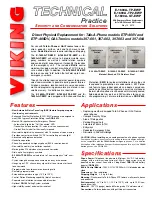
A. DIP Switches
1 2 3 4
ON
BLK-4 Control Module
Switch 1 Switch 3 Description (see section B)
ON
OFF
Ring Detection Only
OFF
ON
Off-Hook/Loop Current Detection Only
ON
ON
Ring and Off-Hook/Loop Current Detection
Switch 2 Ring Cadence Mode (see section C)
ON
Ring Cadence Mode ON - relay remains activated in between rings.
OFF
Ring Cadence Mode OFF - relay is activated only during ringing.
Switch 4 Auxiliary Relay Contacts (see section D)
ON
Wet (12VDC, 100mA maximum)
OFF
Dry (1 Amp maximum @ 30VDC)
2. Loop/Off-hook Indication Only
Place DIP switch
1 OFF
and DIP switch
3 ON
. In this configuration, the
BLK-4
control module will only flash the strobe light
while off-hook (while the emergency phone is in use).
1. Ring Indication Only
Place DIP switch
2
on the
1600A
emergency phone board in the
OFF
position (not shown in the diagram - see
1600A
Emergency Phone Board Programming
section
J
).
Note:
With DIP switch
2
in the
OFF
position, the
1600A
emergency phone
board will not answer an incoming call.
The
LDB-3
control module can monitor for ringing any place along the ringing line. Place
DIP switch
1 ON
and DIP switch
3 OFF
.
3. Both Ring and Loop/Off-hook Indication
If the application requires ring and loop/off-hook indication, place DIP switch
1
and
3
in the
ON
position.
B. Configuring for Ring and/or Loop/Off-Hook Indication
PUSH FOR
VIKING
©
HELP
EMERGENCY
PHONE
CONNECTED
CALL
8.000
1.000
10.00
1.200
12.00
4.800
2.725
2.800
4.800
1.755
"Call Connected" LED
Push for "Help" Button
Grade 2 Braille Label
(6) 0.250 diameter holes
(clearance holes for #10-32
cap head screws, not included)
Marine grade 316 stainless steel faceplate
and push button switch (sealed per IP67)
C. E-1600A-GT-EWP Panel Dimensions