background image

SECTION  TSM

845.1

ISSUE

C

PAGE  8 OF  13

4.

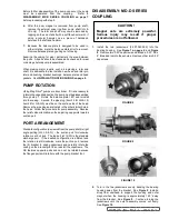
  To  facilitate  disassembly,  it  may  be  necessary  to  slide 

a block of wood under the pump casing or clamp pump 

foot as shown, since the pump alone will not balance on 

foot.  See 

figure 11

.  Remove the (4) 0.50” capscrews 

securing the pump to the coupling bracket.  After parting 

the bracket slightly, it will have a tendency to be drawn 

to one side due to the inner magnet.  Pull the coupling 

bracket completely away.

5.

  There will probably be some liquid left in the canister so  

take the necessary safety precautions.  The canister drain  

is  located  behind  the  mounting  flange  and  near  the 

underside.  Removing plug will drain most of the canister.  

Once the liquid has drained, replace the plugs.

3.

  Set the outer assembly with magnets down on a clean, 

flat  surface  (preferably  not  steel)  to  keep  from  rolling 

around.  Remove temperature probe (if present).

fIGURE 11

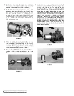
fIGURE 12

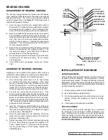
fIGURE 13

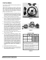
fIGURE 14

7.

  Insert a brass bar through a port between two rotor teeth 

and loosen the capscrew holding the inner magnet onto 

the shaft.  See 

figure 13

.  The 0.437” capscrew has right  

hand  threads  therefore  turn  it  counterclockwise. 

THE 

INNER MAGNET HAS A VERY STRONG MAGNETIC 

FIELD  AND  IS  MOST  DANGEROUS  IN  THE  UN-

ASSEMBLED CONDITION.  THE MAGNET IS QUITE 

HEAVY  AND  WILL  BE  DRAWN  TO  ANY  FERROUS 

OBJECT  OR  SURFACE  CAUSING  POTENTIAL 

PINCHING.    BEWARE  OF  THE  CAUTIONS  LISTED 

ON (PAGE 3).   USE  EXTREME  CARE  SLIDING  THE 

MAGNET  OFF  OF  THE  PUMP  SHAFT.    SET  THE 

MAGNET DOWN ON EITHER END AWAY FROM ALL 

OTHER OBJECTS

.  See 

figure 14

.  Remove the key 

and  the  external  snap  ring  (LQ  &  LS)  and  then  finish 

disassembly of the pump.

6.

  Remove the (8) 0.375” Allen head capscrews holding the 

canister in place then slide the canister off.  See 

figure 

12

.

Summary of Contents for 823

Page 1: ... 10 Adjusting Head Gasket End Clearance 11 Assembly D Series Coupling 11 Troubleshooting 12 Pressure Relief Valves 12 Pressure Adjustment 12 Disassembly Relief Valve 13 Assembly Relief Valve 13 FIGURE 1 LS 825 MD D290 R Complete Unit on Base with Viking C Reducer FIGURE 2 QS 825 MD D450 B Bearing Carrier Footed Pump and Coupling Bracket Jacketed Pump Bracket INTRODUCTION The illustrations used in ...

Page 2: ...Viking Pump product catalog DO NOT attempt to dismantle a pressure relief valve that has not had the spring pressure relieved or is mounted on a pump that is operating AVOID contact with hot areas of the pump and or drive Certain operating conditions temperature control devices jackets heat tracing etc improper installation improper operation and improper maintenance can all cause high temperature...

Page 3: ...This may be a relief valve mounted directly on the pump an inline pressure relief valve a torque limiting device or a rupture disk Do not rely on decoupling of magnets for protection from over pressure this may result in damage to the magnets pump or other equipment 2 If pump rotation is to be reversed during operation pressure protection must be provided on both sides of the pump 3 The relief val...

Page 4: ...table alternate SUGGESTED REPAIR TOOLS The following tools are required to properly repair a Mag Drive pump These tools are in addition to standard mechanics tools such as open end wrenches socket set pliers screw drivers etc Most items can be obtained from an industrial supply house 1 Soft headed hammer 2 Allen wrenches 3 Spanner wrench adjustable pin type for use on end cap Source 482 J H Willia...

Page 5: ...e 19 Idler Bushing 29 Capscrews for Relief Valve 10 Locating Pin 20 Idler Bushing FIGURE 5 EXPLODED VIEW LQ LS SIZE MAG DRIVE PUMPS FIGURE 6 EXPLODED VIEW Q QS SIZE MAG DRIVE PUMP QS SHOWN ITEM DESCRIPTION ITEM DESCRIPTION ITEM DESCRIPTION 1 Brkt Gasket Pilot Face 10 Locating Pin 19 Idler Bushing 2 Brkt Gasket Pilot O D 11 Pipe Plugs 20 Head Gaskets 3 Bracket 12 Casing 21 Idler Pin 4 Capscrews for...

Page 6: ...re original parts and in good condition usually the rest of the pump is also in good condition FIGURE 7 EXPLODED VIEW D SERIES COUPLING ITEM DESCRIPTION ITEM DESCRIPTION ITEM DESCRIPTION 1 Locknut 9 Jack Screws 17 Outer Magnet Assembly 2 Lockwasher 10 Set Screws 18 Bracket 3 Endcap 11 Insert 19 Temperature Monitor Optional 4 Lip Seals 12 Capscrews Bearing Housing 20 Pipe Plug 5 Bearing Spacer Oute...

Page 7: ...on the suction side of the head Remove the pipe plug and reinstall in the other similar hole in the head Follow the procedure for pump assembly Reverse the relief valve orientation so the adjusting cap points towards suction port PORT ARRANGEMENT Standard configuration as viewed from the pump shaft is right angle porting LQ LS Q the suction port for clockwise rotation is at 9 o clock The top port ...

Page 8: ...down on a clean flat surface preferably not steel to keep from rolling around Remove temperature probe if present FIGURE 11 FIGURE 12 FIGURE 13 FIGURE 14 7 Insert a brass bar through a port between two rotor teeth and loosen the capscrew holding the inner magnet onto the shaft See Figure 13 The 0 437 capscrew has right hand threads therefore turn it counterclockwise THE INNER MAGNET HAS A VERY STR...

Page 9: ...If the seal is in good condition slide the endcap over the outer spacer then thread into bearing housing Center the inner spacer so the shaft will slide through the two bearings Thread in the end cap until it makes contact with the outer TRB Tighten the endcap by hand until tight and secure in position with the 2 setscrews 3 Insert the outer magnet shaft through the bearings and the spacers When t...

Page 10: ...gaskets have been put in place 5 Coat the idler pin with suitable lubricant and place the idler on the idler pin in head 6 The head can now be assembled on the pump Tilt the top of the head away from the pump slightly until the crescent enters the inside diameter of the rotor and rotate the idler until its teeth mesh with the rotor teeth Line up mark on head and casing which were previously marked...

Page 11: ...all one 015 and 007 gasket onto the head With the idler on idler pin place head into the pump casing With capscrews tight the feeler gage should fit snugly otherwise gaskets should be added or removed until the proper clearance is attained See Figure 19 FIGURE 19 FIGURE 20 PROCEDURE B If the pump is in the pipeline and not accessible through ports remove the head and remove gaskets Put the head ba...

Page 12: ...he strainer is partially clogged An air leak somewhere in suction line The pump may be running too slow Is motor the correct speed and wired up correctly The pressure relief valve is set too low stuck open or has a damaged poppet or seat The bypass line around the pump is partially open The pump is worn out or has too many gaskets Pump takes too much power stalls motor The liquid is more viscous t...

Page 13: ...FOR A PARTICULAR PURPOSE No officer or employee of IDEX Corporation or Viking Pump Inc is authorized to alter this warranty DANGER Before opening any Viking pump liquid chamber pumping chamber reservoir relief valve adjusting cap fitting etc be sure 1 That any pressure in the chamber has been completely vented through the suction or discharge lines or other appropriate openings or connections 2 Th...

Reviews: