


Page | 28
Step 2.
If the device is a network card and the switch is in the wiring
closet, attach the other end of the cable segment to a modular wall outlet
that is connected to the wiring closet (see the section “Network Wiring
Connections”). Otherwise, attach the other end to an available port on the
switch.
Make sure each twisted pair cable does not exceed 100 meters (328ft) in
length.
NOTE:
Avoid using flow control on a port connected to a hub
unless it is actually required to solve a problem. Otherwise,
back pressure jamming signals may degrade overall
performance for the segment attached to the hub.
Step 3.
As each connection is made, the Link LED (on the switch)
corresponding to each port will light green (1000 Mbps) or amber (100
Mbps) to indicate that the connection is valid.
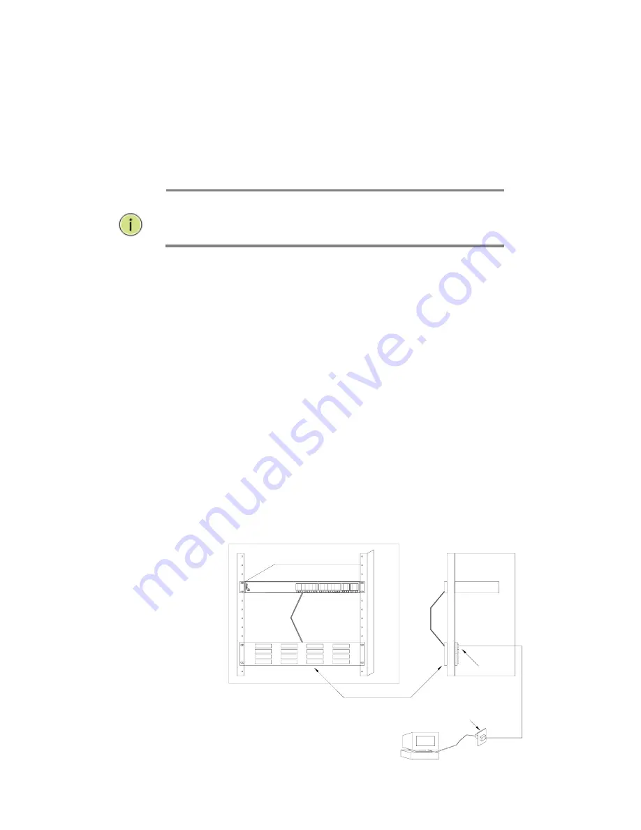
6.4 Network Wiring
Connections
Today, the punch-down block is an integral part of many of the newer
equipment racks. It is actually part of the patch panel. Instructions for
making connections in the wiring closet with this type of equipment
follows.
Step 1.
Attach one end of a patch cable to an available port on the switch
and the other end to the patch panel.
Step 2.
If not already in place, attach one end of a cable segment to the
back of the patch panel where the punch-down block is located and the
other end to a modular wall outlet.
Step 3.
Label the cables to simplify future troubleshooting. See “Cable
Labeling and Connection Records” on page 29.
Sw itch
Equipm ent R ack
(side view )
Patch Panel
Patch-D ow n B lock
W all
Figure 17: Network Wiring Connections
Summary of Contents for MaxiiNet Vi30126 Series
Page 15: ...Page 15 Contact Information 126...
Page 19: ...Page 19 3 4 Vi30126 Front View 3 5 Vi30126 Rear View...
Page 34: ...Page 34 After logging in the following page will appear Full Version Lite Version...
Page 41: ...Page 41...
Page 42: ...Page 42 Section 10 PoE 10 0 PoE Status...
Page 44: ...Page 44...
Page 49: ...Page 49...
Page 55: ...Page 55 Duplex Select Full or Half Duplex for most application select Full...
Page 60: ...Page 60 11 2 Bandwidth Control...
Page 70: ...Page 70 NOTE all ports which are not excluded will be part of the VLAN...
Page 73: ...Page 73 13 1 Drop and Receive Packet 13 2 CRC error packet and Receive Packet...
Page 80: ...Page 80 Section 15 Security 15 0 MAC Address Binding...
Page 89: ...Page 89...
Page 93: ...Page 93...
Page 104: ...Page 104...


