19
5354 788 - 03
Vitorond 200, VD2A Series Installation
Cast Iron Section Assembly
(continued)
Set-up
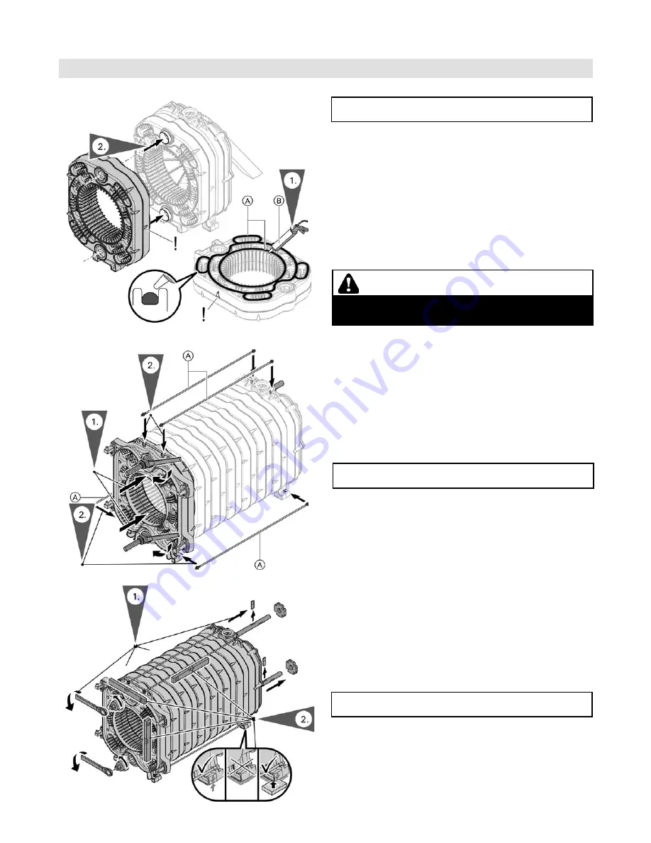
1. Lay each section flat, gasket side facing up
A
.
Apply supplied “Soudal” silicone
B
into grooves
while the cast iron section is laying flat. The next
intermediate sections require sealing all passes,
as shown in Fig. 18.
2. Align the prepared intermediate section with push
nipples on the assembled section. Using a pry bar,
make sure that the push nipples are evenly inserted
into the incoming intermediate section.
IMPORTANT
During the compression procedure, draw in only one
additional section at a time to prevent leaks at the joints.
CAUTION
During the application of the silicone, ensure that the
work area is properly ventilated.
1. Loosen pressure nuts and remove draw tool kit.
2. Ensure that the heat exchanger block is level and
vertical on boiler base. All individual section legs
must properly rest on boiler base.
3. Please clean draw tool kit before crating, ensure that
all parts are included and crate is properly closed
before return shipment.
IMPORTANT
Only release the draw tool once the sections have been
joined with the tie rods.
IMPORTANT
All section feet must be firmly placed on the boiler base.
If necessary, shim section feet.
1. Prepare front section in the same way as previous
sections and align with heat exchanger block utilizing
the draw tool kit in the same fashion as before.
2. Tie rods with washers to top and bottom of heat
exchanger block. Do not overtighten.
Note:
Only hand tighten the nuts on the rods.
Never apply force.


