34
C
B
A
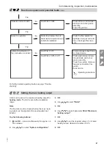
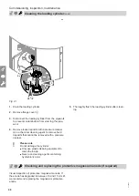
Fig. 28
1.
The lever on the valve must be in position
A
.
2.
Open the on-site DHW supply and a DHW draw-off
point.
3.
Once air stops coming out of the DHW draw-off
point, the DHW cylinder is completely filled.
Checking the connections on the heating water and the DHW side
Danger
Risk of electric shock from escaping heating
water or DHW.
When commissioning and after carrying out
maintenance work, check all water side connec-
tions for leaks.
Naming the heating circuits
In the delivered condition, the heating circuits are des-
ignated "Heating circuit 1", "Heating circuit 2", "Heating
circuit 3" and "Heating circuit 4" (if installed).
If the system user prefers, the heating circuits can be
renamed to suit the specific system.
To enter names for heating circuits:
Operating instructions
Checking the gas type
The boiler is equipped with an electronic combustion
controller that adjusts the burner for optimum combus-
tion in accordance with the prevailing gas quality.
■
For operation with natural gas, no adjustment is
therefore required across the entire Wobbe index
range. The boiler can be operated within the Wobbe
index range 9.5 to 15.2 kWh/m
3
(34.2 to
54.7 MJ/m
3
).
■
For operation with LPG or natural gas M, the gas
type needs to be changed on the control unit (see
following chapter).
1.
Determine the gas type and Wobbe index by ask-
ing your local gas supply utility or LPG supplier.
2.
Record the gas type in the service report.
Commissioning, inspection, maintenance
Filling the DHW cylinder on the DHW side
6130884


