Side Wall Vent Installation
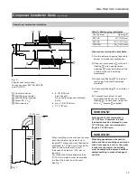
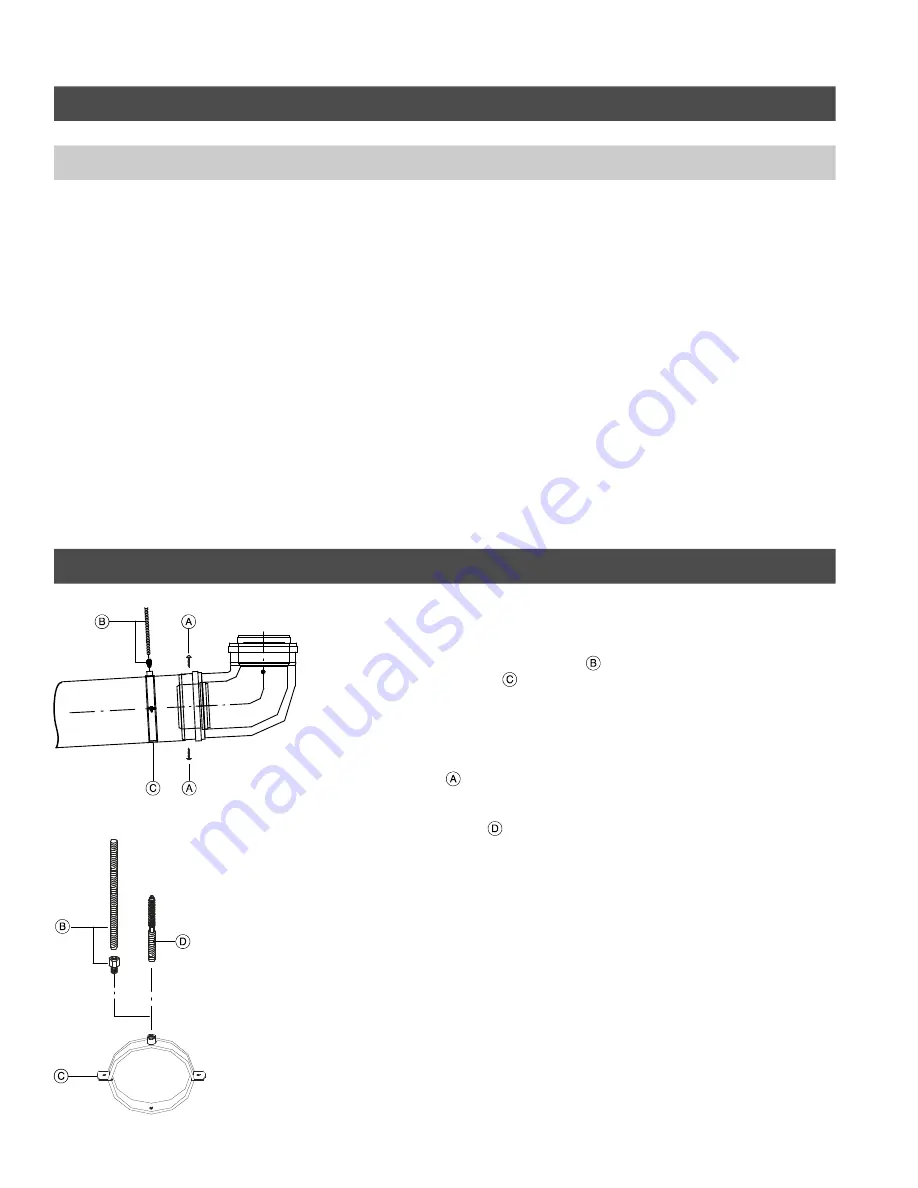
Fig. 10
Fig. 11
20
Component Installation Guide
(continued)
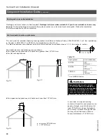
Vent termination location requirements (for installations in the U.S.A.)
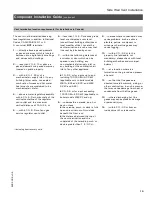
The vent must be installed observing
local regulations in addition to National
Codes, ANSI-Z223.1 or NFPA 54.
A vent must
NOT
terminate...
1.
....less than 7 ft./2.13 m above a
paved sidewalk or a paved driveway
located on public property.
2.
....within 4 ft./1.2 m horizontally
from service regulator vents, electric
and gas meters as well as relief
equipment.
3.
....at least 3 ft./0.9 m above any
forced air inlet located within 10 ft./
3 m.
4.
....less than 1 ft./0.3 m above grade
level or anticipated snow level
(consult local building authorities or
local weather office). Locate the
vent termination in such a way that
it cannot be blocked by snow.
5.
....within 1 ft./0.3 m of a window or
door which can be opened in any
building, any non-mechanical air
supply inlet to any building or the
combustion inlet of any other
appliance.
6.
....in areas where condensation may
cause problems, such as above
planters, patios, or adjacent to
windows where flue gases may
cause fogging.
7.
....within 3 ft./0.9 m to the property
line (advisable, not mandatory;
please check with local building
authorities and municipal bylaws).
8.
....at a location where ice formation
on the ground can present a hazard.
9.
....so that the flue gases are directed
toward brickwork, siding, or other
construction, in such a manner that
may cause damage from heat or
condensate from the flue gases.
10.
....where discharging hot flue
gases may cause property damage
or personal injury.
11.
....within 3 ft./0.9 m from an
inside corner of outside walls.
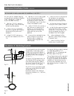
Installation of Anchoring System
The venting system must be securely
supported by an anchoring system
suitable for the weight and design of
the materials employed. To do so, use
supplied mounting clips (see
Fig.
10, Fig. 11).
The joints in the horizontal section of
the Vitodens 200-W venting system
must be secured with the supplied
sheet metal screws
(see Fig. 9) to
prevent the system from sagging .
The 4”/101.6 mm screws
supplied
with the mounting clip provide wall or
ceiling support for a
H
minimum distance of 2”/50.8 mm
H
maximum distance of 3¼”/82.5 mm.
See Fig. 11.
If a longer anchoring system is required
use brass adaptors M8 x
5
/
16
”
(supplied) with
5
/
16
” all-threaded rods
(field supplied). See Fig. 11.
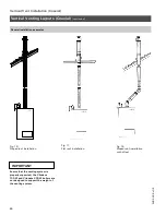
The venting system must be supported
as outlined by one anchor per straight
vent pipe. Viessmann recommends the
installation of the anchor(s) near the
vent joint. See illustration (Fig. 3) of
side wall venting layout on page 13 of
this manual.
5
2
8
5
2
6
8
v
3
.8
5
2
8
5
2
6
8
v
3
.8
Summary of Contents for Vitodens 100-W WB1A-24
Page 78: ...78 5285 268 v3 8 ...
Page 79: ...79 5285 268 v3 8 ...


