58
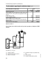
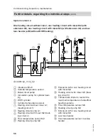
1
Vitodens 200-W
2
Vitotronic 300-K
3
Outside temperature sensor
4
Boiler circuit pump
5
DHW cylinder
6
Cylinder temperature sensor
7
Circulation pump for cylinder heat-
ing
8
Heating circuit with mixer M2 (heat-
ing circuit 2)
9
Flow temperature sensor M2
qP
Heating circuit pump M2
Extension kit for one heating circuit
with mixer M2
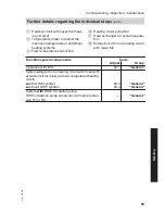
qW
Heating circuit with mixer M3 (heat-
ing circuit 3)
qE
Temperature limiter to restrict the
maximum temperature of underfloor
heating systems
qR
Flow temperature sensor M3
qT
Heating circuit pump M3
qZ
Extension kit for one heating circuit
with mixer M3
qU
Low loss header
qI
Flow temperature sensor, low loss
header
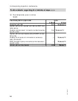
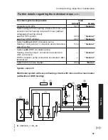
Required codes
Address
Multi boiler system with Vitotronic 300-K
01:2
Note
Codes for multi boiler system, see
Vitotronic 300-K installation and service
instructions
Adjusting the heating curves (only for weather-compensated
control units)
The heating curves illustrate the relation-
ship between the outside temperature
and the boiler water or flow tempera-
ture.
To put it simply: The lower the outside
temperature, the higher the boiler water
or flow temperature.
The room temperature, in turn, depends
on the boiler water or flow temperature.
Settings in the delivered condition:
■ Slope = 1.4
■ Level = 0
Note
If the heating system includes heating
circuits with mixers, then the flow tem-
perature of the heating circuit without
mixer is higher by a selected differential
(8 K in the delivered condition) than the
flow temperature of the heating circuits
with mixers.
The differential temperature is adjusta-
ble via coding address "9F" in the "Gen-
eral" group.
Commissioning, inspection, maintenance
Further details regarding the individual steps
(cont.)
5623 520 GB


