background image

19

5680 011 -10

Viessmann AirflowPLUS AH2A Installation, Operating and Service

Installation

 Panels 

(continued)

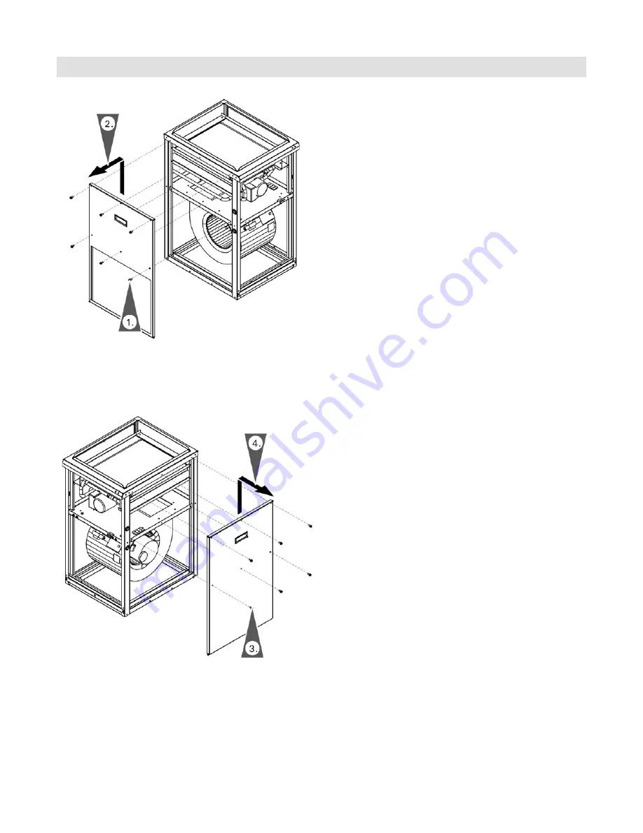
To change the duct connection side of the air handler 

for vertical installation, the right and left side panel can 

be interchanged. To interchange the panels refer to the 

following instructions.

1.   Remove the retaining screws and set aside.

2.   Remove the side panel by pulling up on the handle  


and then out.

3.   Remove the retaining screws from the panel on  


the opposite side and set aside.

4.   Remove the side panel by pulling up on the handle  


and then out.

Summary of Contents for AirflowPLUS AH2A-213

Page 1: ...mann AirflowPLUS Installation Service and Operating Instructions for use by heating contractor Viessmann AirflowPLUS AH2A series Hydronic forced air handler Product may not be exactly as shown Read and save these instructions for future reference IMPORTANT ...

Page 2: ...r professional service annually before the heating season begins Operating and service documentation It is recommended that all product documentation such as parts lists operating and service instructions be handed over to the system user for storage Documentation is to be stored near air handler in a readily accessible location for reference by service personnel WARNING Inhaling of fiberglass woo...

Page 3: ...nd Sizing 9 Compatibility Charts 9 BeforeSet up 11 Minimum Clearances 11 Dimensions 12 Heating Circuit Pumps 13 Installation 13 Installation Examples 14 Horizontal installation 14 Vertical installation 15 Proper Piping Practice 16 Connecting to the Heating System 16 Removing the blower shipping Bracket 17 Opening the Air Handling Unit 17 Panels 18 Accessing the Connection Board 21 Vitodens 100 WB1...

Page 4: ...ct for Air Handler Vitodens 100 WB1B 40 Illuminated Alarm Indicator 41 Home freeze protect 41 Heat exchanger freezing protection control 41 Cooling lockout 41 Temperature sensor failure 41 Audible Alarm Indicator 41 Alarm Relay and LED Fault Codes 42 Control LED flash codes 42 Alarm 42 Checking ECM DC Fan Motor Connections 43 Troubleshooting 44 Service and Maintenance 48 Checking temperature senso...

Page 5: ... avoided could result in death serious injury or substantial product property damage Indicates an imminently hazardous situation which if not avoided may result in minor injury or product property damage Helpful hints for installation operation or maintenance which pertain to the product This symbol indicates to note additional information This symbol indicates that other instructions must be refe...

Page 6: ...qualified and experienced in the installation service and maintenance of hot water heating equipment There are no user serviceable parts on the air handler Please carefully read this manual prior to attempting start up maintenance or service Any warranty is null and void if these instructions are not followed For information regarding other Viessmann System Technology componentry please reference ...

Page 7: ... B 88 and or B 743 standards High density aluminum fins provide maximum heat transfer for small coil surface Fan and motor The ECM fan is a wide body dynamically balanced for extra quiet operation Multi directional sleeve bearing motors allow mounting in any direction for maximum installation flexibility Circulating pump The internal circulating pump is matched for maximum performance All Airflow ...

Page 8: ...d sensor which will help prevent the home from freezing due to a faulty thermostat Should the ambient temperature get too low the control will turn the air handler on automatically and maintain the home at approximately 40 F 4 C Note this feature will only work if the boiler is turned on and the air handler has power While in Home freeze protect mode the alarm relay and red light will be on Refer ...

Page 9: ... 222 B2TB 19 Vitodens 222 B2TB 35 Vitodens 200 B2HB 19 Vitodens 200 B2HB 26 Vitodens 200 B2HB 35 Vitodens 200 B2HB 45 Vitodens 200 B2HB 57 Vitodens 200 B2HA 45 Vitodens 200 B2HA 60 Vitodens 200 B2HA 80 Vitodens 200 B2HA 88 Vitodens 200 B2HA 100 Vitodens 200 B2HA 112 Vitodens 200 B2HA 150 Vitocrossal 300 CU3A 26 Vitocrossal 300 CU3A 35 Vitocrossal 300 CU3A 45 Vitocrossal 300 CU3A 57 Compatibility C...

Page 10: ... temperature 120 F 51 MBH 140 F 74 MBH 160 F 90 MBH 180 F 115 MBH Vitodens 100 WB1B 26 Vitodens 100 WB1B 35 Vitodens 222 B2TB 19 Vitodens 222 B2TB 35 Vitodens 200 B2HB 19 Vitodens 200 B2HB 26 Vitodens 200 B2HB 35 Vitodens 200 B2HB 45 Vitodens 200 B2HB 57 Vitodens 200 B2HA 45 Vitodens 200 B2HA 60 Vitodens 200 B2HA 80 Vitodens 200 B2HA 88 Vitodens 200 B2HA 100 Vitodens 200 B2HA 112 Vitodens 200 B2HA...

Page 11: ...UTION The air handler must be installed in such a way that electrical components are protected from water spraying splashing etc during operation and service Horizontal Installation Vertical Installation a 24 in 610 mm b 12 in 305 mm These dimensions reflect the recommended service clearance for the air handler only ensure adequate clearance is left for the installation of ducting piping and elect...

Page 12: ...584 mm 28 711 mm b in mm 18 457 mm 22 559 mm 22 559 mm c in mm 32b 826 mm 34b 876 mm 34b 876 mm d in mm 22a 572 mm 24e 620 mm 24e 620 mm e in mm 23b 597 mm 25b 650 mm 25b 650 mm f in mm 2 51 mm 1c 44 mm 1c 44 mm g in mm 3 76 mm 3f 92 mm 3f 92 mm h in mm 24c 629 mm 25 635 mm 30 762 mm Legend A Heating water supply connection B Heating water return connection Using the adjustable levelling feet can ...

Page 13: ...with front cover facing down An adequately sized drain pan and drain connection must be installed under the appliance if installed in or above a finished space If installed in an unfinished space a drain pan is not provided necessary precautions must taken to ensure proper drainage of water in the event of a water leak e g Floor drain sump pump moisture alarm This appliance shall not be installed ...

Page 14: ...ngth to support air handler weight of 150 lbs 68 kg and connected accessory fittings and materials Note Return air openings are provided in both the bottom and side panels CAUTION Return air openings shall not be installed in back panel For horizontal installation over a finished space A field fabricated auxiliary drain pan with drain pipe is required to prevent damage by overflow due to blocked c...

Page 15: ...voltage leads and routed through knockouts provided Discharge air Cold air return Vertical installation The A C coil is installed in the upstream air flow of the Viessmann AirflowPLUS air handler This will require the use of the remote return air temperature sensor mounted upstream of the A C coil See page 41 for additional information regarding the remote return air temperature sensor Snap round ...

Page 16: ...n and start up of the boiler Make sure the heating device is turned off during air handler installation and service Ensure system has been filled and all air is purged from the system before turning on the heating boiler Duct work All duct designs must be designed to conform with ARI Manuals J and D or local codes and requirements To minimize fan noise in the living space it is recommended that th...

Page 17: ... panel retaining screws and set aside 2 Tilt the lower front panel forward at the top and lift out 3 Remove the upper front panel retaining screws and set aside 4 Slide the upper front panel down and pull out Installation Opening the Air Handler Unit 1 Remove the bracket retaining thumb screws and discard 2 Remove the bracket and discard ...

Page 18: ...ons For horizontal installations remove the bottom panel and install it to the left side panel opening Horizontal installation 1 Remove the bottom panel retaining screws and set aside 2 Remove the bottom panel and set aside Note The fan tray is preinstalled into the bottom of the air handler 3 Install the bottom panel to the left side of the air handler opening and secure with the retaining screws...

Page 19: ...stallation the right and left side panel can be interchanged To interchange the panels refer to the following instructions 1 Remove the retaining screws and set aside 2 Remove the side panel by pulling up on the handle and then out 3 Remove the retaining screws from the panel on the opposite side and set aside 4 Remove the side panel by pulling up on the handle and then out ...

Page 20: ...anel removed from step 2 by placing the panel into the air handler and pushing down with the handle 6 Reinstall the retaining screws Note To install the filter tray see page 19 7 Install the side panel removed from step 4 by placing the panel into the air handler and pushing down with the handle 8 Reinstall the retaining screws ...

Page 21: ...nect the field supplied ducting to the filter tray as required Panels continued Accessing the Connection Board Installation Accessing the connection board with hinged cover 1 Remove the blower assembly retaining screws and set aside 2 Slide the blower assembly forward 3 Remove the 2 retaining screws from the connection board cover 4 Swing the cover up to open IMPORTANT Careful not to slide the blo...

Page 22: ...Wiring Installation For more details refer to the Vitodens 100 W Installation Instructions Connect call for heat K2 relay of the air handler to the RT connection X4 terminals 3 and 4 of the Vitodens 100 WB1B power pump module Power Pump Module PPM Viessmann AirflowPLUS Connection Board Thermostat ...

Page 23: ... call for heat K2 relay of the air handler to the DHW connection X4 terminals 1 and 2 of the Vitodens 100 WB1B power pump module In a system where the DHW contact is not used the DHW contact may be used as a second set point this set point is not affected by outdoor reset Refer to page 40 for additional information Power Pump Module PPM Viessmann AirflowPLUS Connection Board A A Heating circuit co...

Page 24: ...elay of the air handler to terminals DE1 of the integrated EA1 module For coding and programming requirements refer to page 39 Refer to the appropriate boiler Installation Instructions HO1B Connections Vitodens 200 W B2HA and B2HB Vitodens 222 F B2TA and B2TB Vitocrossal 300 CU3A Viessmann AirflowPLUS Connection Board Thermostat ...

Page 25: ...tivate an external device to alert the user that an alarm condition exists Alarm conditions include Heat exchanger freeze protection limit exceeded Return air temperature is too low Exhaust air temperature is too cold Cooling lockout If a freeze protect cycle is initiated 3 times within a single cooling cycle the system goes into cooling lockout mode The cooling cycle is stopped and new cooling cy...

Page 26: ...ystem preference Remote Return Air Sensor T5 The remote return air sensor is preinstalled within the Viessmann AirflowPLUS cabinet complete with a 10 ft 3 m cable lead for remote sensor locations Remove the strap from the sensor lead and install in the required location Sensor Locations It should be noted that this is a precautionary measure and is not designed to prevent water line freezing in si...

Page 27: ...t the set value Override Settings System Select Dip Switch Settings Four system settings are available Two for use when the evaporator is in the supply air stream two for use when the evaporator is in the discharge air stream In each configuration the hot water threshold of 85 F or 110 F 29 C or 43 C may be selected this ensures that only warm air is available during heating operations S5 S6 S7 S8...

Page 28: ...erating and Service 5680 011 10 28 Installation Door Safety Switch The door safety switch is located on the internal center support panel Once the lower front panel is removed the switch will disconnect power to the control board and fan motor ...

Page 29: ... connected to the screw terminals located on the control board inside the air handler They should be connected as follows RH RC power 24VAC W heating Y cooling if present G continuous run fan if present on thermostat A C condenser must be connected to position AC relay Y C only Improper connections will result in loss of protection functions Installation Note Before making the connection to the th...

Page 30: ...Line PMP XFO XFI ECM Power ECM Control Power Connection Terminal WARNING Incorrectly executed electrical installations can lead to injuries from electrical current and result in appliance damage WARNING If system components are not grounded serious injury from electric current can result if an electrical fault occurs Connect the appliance and pipework to the equipotential bonding of the building i...

Page 31: ... set up by the selected dip switch settings See setting fan speed pages 32 33 and 34 Cooling control A 24VAC input is provided to control the cooling function When the thermostat calls for cooling 24VAC is applied to the Y contact and a cooling cycle will be initiated Note the heating cycle control will be ignored while a cooling cycle is in progress If the cooling control is turned off during the...

Page 32: ... 726 Cooling CFM 1175 1290 1034 925 1010 814 Heating CFM 675 740 594 550 605 484 Cooling CFM 750 825 660 600 660 528 Cool Fan Speed Switches 5 6 OFF OFF 1175 ON OFF 925 OFF ON 750 ON ON 600 Cool Fan Speed Profiles Switches 7 8 Pre Run Time Min Motor Short Run Time Min Motor Motor OFF Time Min Motor OFF OFF 5 82 2 88 2 75 ON OFF 3 82 2 88 2 75 OFF ON 2 82 4 75 ON ON 4 75 Note Power to the Viessmann...

Page 33: ...Options Set at dip switch S2 Installation Heat Fan Speed Switches 1 2 OFF OFF 1300 ON OFF 980 OFF ON 675 ON ON 760 Adjust Fan Speed Switches 3 4 OFF OFF ON OFF OFF ON OFF OFF ON OFF OFF ON Heating CFM 1300 1430 1140 980 1050 860 Cooling CFM 1640 1804 1440 1270 1400 1100 Heating CFM 760 830 660 760 830 660 Cooling CFM 980 1050 860 740 800 650 Cool Fan Speed Switches 5 6 OFF OFF 1640 ON OFF 1270 OFF...

Page 34: ...ble Options Set at dip switch S2 Heat Fan Speed Switches 1 2 OFF OFF 1650 ON OFF 1590 OFF ON 1470 ON ON 1320 Adjust Fan Speed Switches 3 4 OFF OFF ON OFF OFF ON OFF OFF ON OFF OFF ON Heating CFM 1650 1800 1480 1590 1750 1430 Cooling CFM 1875 2060 1680 1730 1900 1560 Heating CFM 1470 1620 1320 1320 1450 1180 Cooling CFM 1620 1780 1450 1500 1650 1350 Cool Fan Speed Switches 5 6 OFF OFF 1875 ON OFF 1...

Page 35: ...t work 3 Full port isolation valves MUST be provided Restrictive valves will limit performance 4 Is outdoor cooling unit contactor wired to screw terminals on controller to provide hard start protection 5 Are thermostat connections correct including cooling and continuous run connections 6 Have the packing materials been removed from the blower and the pump 1 REMOVE PACKING MATERIALS FROM LEFT SID...

Page 36: ...re for 5 sensors The Air Handler allows the attachment of up to five sensors The LED sequence for displaying five sensors uses a bicolor LED to indicate the sensor number followed by the sensor temperature reading The sequence starts with a one red blink to indicate sensor T1 this is followed by the temperature indication using green blinks as described above This is followed by a 2 blink red LED ...

Page 37: ... in blower assembly 4 Reinstall retaining screw 1 Set the top of the upper front cover in place and slide up 2 Reinstall retaining screws 3 Set the bottom of the lower front panel in place and slide up 4 Reinstall retaining screws Installing connection board with removable cover 1 Install the connection board cover 2 Secure cover with retaining screw 3 Slide in blower assembly 4 Reinstall retainin...

Page 38: ...avior is noted the LED will display an indication to indicate the condition F C x 1 8 32 e g 24 x 1 8 32 75 2 F Heating mode On a call for heat from the thermostat the circulating pump will turn on Giving the pump 15 sec to heat the coil the fan will activate heating the home until the thermostat is satisfied Once the thermostat is satisfied the circulating pump will shut down and fan will continu...

Page 39: ... the heating curve corresponding with the heating curve chart The set point will be calculated from the design boiler water temperature associated with the heating curve selected and reset from the actual outdoor air temperature Setting the dial between 1 and 6 will select the corresponding curve from the chart The dot between 4 and 5 is the factory default curve The display tr indicates when a he...

Page 40: ...boiler in a multi zone system Without DHW the DHW contact of the boiler can be used as a second temperature setpoint for the air handler When the air handler call for heat closes the boiler supply temperature will automatically adjust to 172 F 78 C There is no adjustment available for this temperature set point Dial setting 0 6 boiler supply water temperature automatically adjusted to 172 F 78 C r...

Page 41: ...ms with the evaporator in the return air stream Freeze protect is also initiated when the discharge air temperature is less than 41 F 5 C the unit will go into freeze protection mode 3 Cooling lockout If the A C coil Freeze Protect Cycle 2 above is initiated three times within the same cooling cycle the system goes into Cooling Lockout Mode During this time the cooling cycle is disabled and new co...

Page 42: ...displayed in the following order Flash Code Explanation Cause RRR Cooling Lockout Page 41 RRG Freeze protect cycle in process Page 41 GRR A C Delta exceeded 3 times Page 41 RGR High A C coil delta Page 25 RGG Low ambient temperature Page 41 R Red G Green Alarm Alarm Relay is on when an unusual condition is detected The connector is a two terminal connector that provides a contact closure when the ...

Page 43: ...nsors operate as system safeties only Checking ECM DC Fan Motor Connections Pin number 1 Common C1 2 W W1 3 Common C2 4 Delay tap select 5 Cool tap select 6 Y1 7 Adjust tap select 8 Output 9 Return reversing valve heat pump only 10 Humidistat BK 11 Heat tap select 12 24VAC R 13 2nd stage heat EM W2 14 2nd stage cool Y Y2 15 Fan G 16 Output ECM Motor Control Connector female Control male Service ...

Page 44: ...p exercise function will help prevent pump seizing Pump is noisy at start up Air is present in heating loop If sound has not diminished within 1 minute purge air in accordance with the Start Up procedures Insufficient or no heat Plugged air filter or coil Refer to Maintenance section for filter care and coil cleaning Air in heating loop purge system Inlet and outlet connections to air handler back...

Page 45: ... after 5 minute delay The air handler internal water coil freeze sensor T3 is activated by low air temperature Check for poor air flow restrictions plugged filters low refrigerant charge 3 protect cycles occur in a single cooling cycle cooling cycle is inhibited sensor T3 indicates 7 green 7 green alarm buzzer ON Refer to cooling lockout chart Yes Yes Yes Yes Continue Continue Yes Yes Water coil f...

Page 46: ...ng can only be reactivated by cycling the power OFF and then ON Inadequate air flow plugged filter extreme ESP low refrigerant Outdoor ambient or thermostat set too low Yes Yes Yes Yes Yes Continue Continue No Observe each sensor code and record related flash codes as shown on the housing mounted LED Refer to page 42 Cooling lockout This feature is initiated if three freeze protect cycles occur wi...

Page 47: ...hours The alarm buzzer is on The red housing mounted LED is illuminated after 5 minutes of power on The housing mounted LED will flash an error code Record colors and number of flashes 5 cycles min Refer to chart on page 42 for identification If 8 red flashes followed by 8 red flashes repeats after a specific sensor then replace that sensor Note the alarm buzzer can be silenced for 24 hours by cyc...

Page 48: ...n this case the absent sensor temperature is replaced by one long green blink following the red sensor number blinks Failed Sensors When a sensor is incorrectly installed or defective the LED indication will substitute red 8 8 for a normal temperature reading The alarm beeper will also beep periodically to indicate a problem The alarm beeper will sound for 1 minute after power on and then stop In ...

Page 49: ...his system layout An undersized pump may cause short cycling and or improper operation of the boiler Legend A Vitocrossal 300 CU3A high mass boiler B System fill with expansion tank C Viessmann AirflowPLUS air handler D Thermostat field supplied E Indirect fired DHW storage tank Additional Information IMPORTANT Refer to page 24 for the Viessmann AirflowPLUS connection to external heat demand of th...

Page 50: ...n diffusion barrier tubing All components on the secondary side of the heat exchanger must be made of corrosion resistant materials The 3 way mixing valve built in to achieve the low temperature level of the under floor heating circuit is controlled by an accessory kit for a heating circuit with mixing valve Legend A Vitocrossal 300 CU3A high mass boiler B System fill with expansion tank C High te...

Page 51: ...systems employing non oxygen diffusion barrier tubing All components on the secondary side of the heat exchanger must be made of corrosion resistant materials The 3 way mixing valve built in to achieve the low temperature level of the under floor heating circuit is controlled by an accessory kit for a heating circuit with mixing valve Legend A Vitodens 222 F B2TA B boilers B System fill with expan...

Page 52: ... barrier tubing All components on the secondary side of the heat exchanger must be made of corrosion resistant materials The 3 way mixing valve built in to achieve the low temperature level of the under floor heating circuit is controlled by an accessory kit for a heating circuit with mixing valve Legend A Vitodens 200 B2HA B boilers B System fill with expansion tank C High temperature heating loo...

Page 53: ...e heating system does not include a DHW storage tank connected to the boiler the DHW demand contacts of the boiler may be connected to the Viessmann AirflowPLUS heat demand use the DHW temperature set point to set the desired supply temperature to the air handler Legend A Vitodens 100 WB1B boiler B System fill with expansion tank C Viessmann AirflowPLUS air handler D Thermostat field supplied E Sw...

Page 54: ... the system flow rates are unknown The low loss header is available as accessory part Please note location of expansion tank Legend A Vitodens 100 WB1B boiler with CombiPLUS B System fill with expansion tank C High temperature heating loop D Viessmann AirflowPLUS air handler E Thermostat field supplied F Switching relay heating circuit control field supplied G Low loss header or closely spaced tee...

Page 55: ...de of corrosion resistant materials The 3 way mixing valve built in to achieve the low temperature level of the under floor heating circuit is controlled by an accessory kit for a heating circuit with mixing valve Legend A Vitocrossal 300 CU3A high mass boiler Vitodens 200 B2HA B boilers shown B System fill with expansion tank C High temperature heating loop D Viessmann AirflowPLUS air handler E T...

Page 56: ... 4X pipe diameter is strongly recommended if the maximum water flow rate in the application concerned exceeds the maximum or minimum flow rates of the boiler or if the system flow rates are unknown The low loss header is available as accessory part Please note location of expansion tank Sizing of field supplied pumps are critical for proper boiler operation in this system layout An undersized pump...

Page 57: ... 22c x 18 x 32b 578 x 457 x 825 23 x 22 x 34b 584 x 559 x 876 28 x 22 x 34b 711 x 559 x 876 Supply air opening in mm 16 x 20 406 x 508 20 x 20 508 x 508 20 x 25 508 x 635 Return air opening in mm 14 x 18 356 x 457 18 x 18 457 x 457 18 x 23 457 x 584 Weight lb kg 85 39 100 45 110 50 Circulating pump Type Grundfos 15 58RU Volts AC 115 115 115 Motor horsepower hp 1 25 1 25 1 25 Capacitor MFD VOLTS 10...

Page 58: ...z 12A Main Disconnect Switch Door Safety Switch Viessmann AirflowPLUS Connection Board optional two stage cooling shown External Connections Internal Connections Power Connection Terminal If any of the original wires as supplied with the appliance must be replaced it must be replaced with the exact equivalent CAUTION Label all wires prior to disconnection when servicing controls Wiring errors can ...

Page 59: ...p select 6 Y1 7 Adjust tap select 8 Output 9 Return valve heat pump only qP Humidistat BK qQ Heat tap select qW 24VAC R qE 2nd stage heat EM W2 qR 2nd stage cool Y Y2 qT Fan G qZ Output Electrical Connections continued Legend 1 Diagnostic LED 2 Ambient temperature sensor 3 Return air temperature sensor 4 Discharge air temperature sensor 5 Freeze protection temperature sensor 7 Supply water tempera...

Page 60: ...t for fan motor 0011 Blower housing 0012 Blower wheel 0013 Hot water coil 0014 Circulation pump head GF UPS15 58RU 0015 Sensor for return air T5 0016 Sensor for AC discharge air T4 1 0017 Sensor for freeze protect T3 0018 Sensor for supply water T1 0019 Pump support block 0020 Sensor ambient T6 0021 Diagnostic LED 0023 Door safety switch 0024 Terminal block main power supply 0025 Transformer 120VA...

Reviews: