background image

66250203-EN - V0.3 - 10/07/15

10

4000 Series Vandal Resistant Range

Art. 4212V-4212RV - Installation instructions

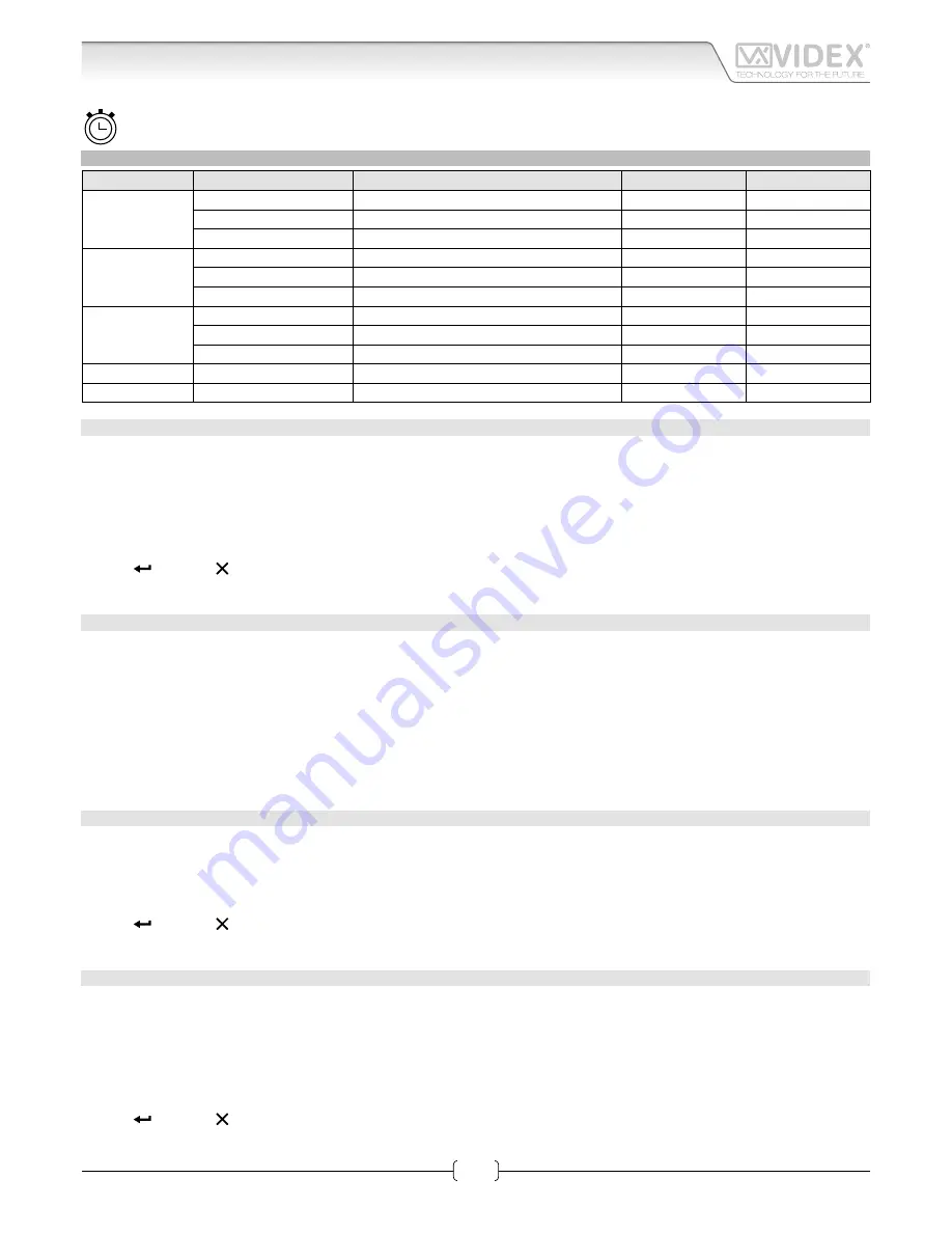
TIME PARAMETERS

Time par. menu Parameter Name

Programming method

Permission

Default value

1: Clock

Clock format

By panel and PC software

All

0-23

Clock

By panel and PC software

All

/

BST/GMT Enable/disable By panel

All

Enabled

2: Date

Date format

By panel and PC software

All

European

Date

By panel and PC software

All

/

Day

By panel

All

/

3: Trade

Trade enable

By panel and PC software

All

Disabled

Trade start

By panel and PC software

All

/

Trade end

By panel and PC software

All

/

4: Relay Time

Relay time

By panel and PC software

Only Engineer

2 s

5: Speech Time

Speech time

By panel and PC software

Only Engineer

120 s

CLOCK FORMAT

It changes the clock format shown on the home page.

Select either 12 hour or 24 hour clock format.

Modify routine

•  press 

“1”

 to enter the clock menu;

•  press 

“1”

 to enter into edit mode;

•  press 

“1”

 to switch from 1-12 to 0-23 and viceversa;

•  press 

 to save or   to exit edit mode without saving.

CLOCK

Set the time on the door panel.

Modify routine

•  press 

“1”

 to enter the clock menu;

•  press 

“2”

 to enter edit mode;

•  enter the hour, minutes and seconds (all fields are composed of two digits). After entering two digits to set the hour it automati-

cally advances to the minutes and then to seconds.If in 12 hour clock format, after seconds it is possible to select AM/PM;

•  After setting the last parameter the time will be saved.

BST/GMT ENABLE/DISABLE

Enable or disable BST/GMT automatic Summer/Winter time adjustment.

Modify routine

•  press 

“3”

 to enter edit mode;

•  in edit mode, press 

“3”

 to enable or disable the facility;

•  press   to save or   to exit edit mode without saving.

DATE FORMAT

It changes the date format shown on the home page.

The date can either be in EU (dd/mm/yy) or US (mm/dd/yy) format.

Modify routine

1.  press 

“2”

 to enter the date menu;

2.  press again 

“1”

 to enter into edit mode;

3.  press 

“1”

 to switch from EU to US and viceversa;

4.  press   to save or   to exit edit mode without saving.

Art. 4212V - 4212RV 

 Audio/video digital front panel 

Programming

Summary of Contents for 4212RV

Page 1: ...alanced V1 V2 Coax V2 V V1 not used Balance V PB CHIP Made in Italy 12T GNDV V2 V V1 PTE TRD NO C NC SL BS L 12 GND OC OUTPUT D0 D1 LR LG WIEGAND A B GND RS485 Dry contact output Capacitor discharge R...

Page 2: ...era provides the best quality of view in any light condition and the wide angle camera provides a viewing angle of 170 degrees The camera can be set to work with composite video signal coax cable or b...

Page 3: ...n door if enabled see Trade on pag 12 a valid Access code the door will be open or NOT FOUND message will appear To delete digits or exit page press HOW TO CALL AN APARTMENT From stand by mode enter a...

Page 4: ...nctions to scroll back to scroll forward to alternate between capital and lower case letters For instance to type the name VIDEX it is necessary to press 3 times 8 button V 3 times 4 button I 1 times...

Page 5: ...n COMPATIBILITY MODE please refer to User parameters Code on pag 7 From Programming menu press 1 to enter the user menu then 1 to modify a user find the user by name or flat press 3 and enter in User...

Page 6: ...usly select search by key option he has to pass card fob over the symbol if searched key is present the user tag modify page will appear pressing 1 to enable disable the key press to save or to exit w...

Page 7: ...ve or to delete characters or exit edit mode without save FLAT The flat number is entered by the visitor to call a flat It can be 1 to 6 digits long Modify routine select user searching by name or fla...

Page 8: ...edit mode without save PHONE ID The phone ID represents the address of the intercom to call Set by the 8 way dip switches in the intercom Modify routine select user searching by name or flat press 6 t...

Page 9: ...en in standby Enter the string and press The have a blank line enter one or more space characters Modify routine press 1 2 or 3 to enter into edit mode enter the string press to save or to delete char...

Page 10: ...o switch from 1 12 to 0 23 and viceversa press to save or to exit edit mode without saving CLOCK Set the time on the door panel Modify routine press 1 to enter the clock menu press 2 to enter edit mod...

Page 11: ...ess 3 to enter the trade menu press 1 to enter edit mode press 1 to enable or disable the facility press to save or to exit edit mode without saving TRADE START TRADE END The beginning and end times o...

Page 12: ...nd and only when TRD is shorted to 0V It must be between 3 to 6 digits and different to all other codes Entering the correct code when the above requirements are met will open the door for the program...

Page 13: ...ave or to delete characters or exit edit mode without saving MASTER Specifies if the panel is a master or a slave On each bus there should only be one master all other panels on that bus should be sla...

Page 14: ...memory location PROXIMITY ACCESS MODE This parameter specifies if the proximity reader works in a self contained standalone mode or is connected via a Wiegand interface to an external controller such...

Page 15: ...called is pronounced singularly i e 123 one two three In COMBINED mode number called is pronounced all in one i e 123 one hundred and twenty three Modify routine press 2 to enter into edit mode press...

Page 16: ...CTION TERMINALS JUMPERS Dry contact output Capacitor discharge SWITCHES Balanced V1 V2 Coax V2 V V1 not used RS485 BUS TERMINATION Open Close CONNECTION TERMINALS 12T 12Vdc Camera power supply unit GN...

Page 17: ...66250203 EN V0 3 10 07 15 17 4000 Series Vandal Resistant Range Art 4212V 4212RV Installation instructions Art 4212V 4212RV Audio video digital front panel...

Page 18: ...66250203 EN V0 3 10 07 15 18 4000 Series Vandal Resistant Range Art 4212V 4212RV Installation instructions Art 4212V 4212RV Audio video digital front panel...

Page 19: ...out hole in the box 2 Make all the connections on the removable terminal blocks Fig 2 then plug back into the panel Fig 3 setup the dip switches as per provided connection diagram or instruction sheet...

Page 20: ...ox fix surface box to the wall using the screws G Fig 3 4 Connect the wires using a terminal screw driver then setup the dip switches as per provided connection diagram or instruction sheet then power...

Reviews: