


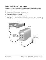


Step 3: Connecting Looping Cables (Kollector Force only)
Looping cables are required only when you wish to retrieve video (output) from the Kollector Force. The
purpose of the cables is to transmit video signals to a second transmitter. Each cable transmits 8 video
signals - Looping 1 transmits signals from cameras 1 to 8 and Looping 2 from cameras 9 to 16.
To connect the cables:
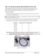
1. Using the two provided Video Looping Cable Assemblies, insert the large D-type connector end into one
of the two Video Looping Output ports.
Note: If the D-shell connector if not used, or if any of the BNC on the looping cable are not used, the
connector must be terminated with 75 ohms.
2. Connect each of the remaining BNC-F connectors to the Video (Camera) Input ports, as defined in the
following table. In order to connect the video, male-to-male BNC cables are required (not included).
Wire Label
Looping 1 Cameras
Looping 2 Cameras
Video 1/9
1
9
Video 2/10
2
10
Video 3/11
3
11
Video 4/12
4
12
Video 5/13
5
13
Video 6/14
6
14
Video 7/15
7
15
Video 8/16
8
16
NOTE: Each BNC cable is labeled for the relevant channel. For example V6680 VIDEO 2/10 (green
wire) transmits video from camera 2, if the D type is connected to Looping No. 1, or camera 10 if
connected to Looping No. 2. Each channel (wire) is designated a unique color.
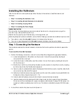
Eight BNC Connectors
D Type Connector
Eight BNC Connectors
D Type Connector
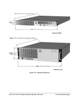
Figure 3-11: Looping Cable
XX112-06-01 Rev 911 Kollector Network Digital Video Recorders
Installation
•
21


