


•
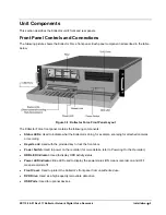
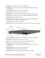
Speaker Output:
Mini phono-type connector used for sound card audio output.
•
LCD Monitor Output:
Used for digital video output to a monitor. DVI to HDMI converter provided.
•
VGA Monitor Output:
Used to connect to a VGA monitor.
•
Auxiliary Fan:
Used to cool the unit during operation.
•
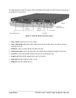
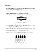
Relays:
16 x 60 V, 1.0 A. Used to control optional equipment connected to the Kollector Force.
•
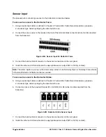
Sensors:
Used to connect sensors to the Kollector Force.
•
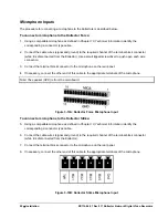
Microphones:
Used to connect microphones to the Kollector Force.
•
Tx/Rx:
Used to connect COM controlled devices (such as: PTZ, external joystick control, and so on) to
the Kollector Force (COM 4).
Note: Rx not currently available.
•
RS422/485:
COM 3 used as an optional port to control PTZ via a V1400X-IDL.
•
Video Matrix Out:
BNC video outputs used to connect analog display monitors to the Kollector. For more
information on the switching Matrix, refer to
Chapter 3, Configuring the ViconNet System
in the Kollector
Software Manual.
•
Auxiliary Fan:
Used to cool the unit during operation.
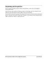
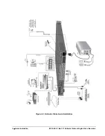
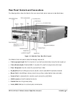
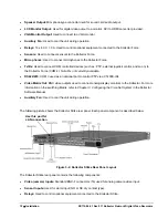
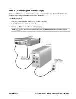
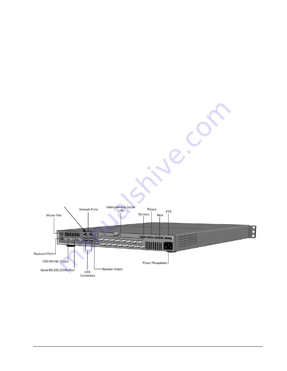
The following picture shows the Kollector Strike rear panel. Each panel component is described below.
Use this port for
LAN connection
Figure 3-4: Kollector Strike Rear Panel Layout
The Kollector Strike rear panel contains the following components:
•
Video (camera) Inputs:
Standard BNC-F connectors (16) used for analog camera video input.
•
Sensor Inputs:
Used for alarm input (NO or NC dry contact type).
•
Relays:
Used to control optional equipment connected to the Kollector Strike.
12
•
Installation
XX112-06-01 Rev 911 Kollector Network Digital Video Recorders