


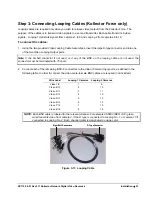

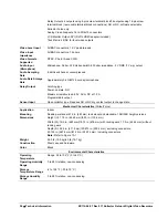
Step 2: Connecting External Hardware to the Kollectors
The connection of external hardware to the Kollectors requires simple hand tools. Use a small tipped
screwdriver to push open or release each wire connection, as necessary. Mating connectors are provided in
the accessory kit. Do not apply power or plug-in the recorder to any outlet until instructed to do so.
WARNING: Disable the AC power to prevent installer injury and damage to the unit.
Connect external devices as follows:
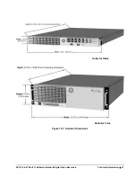
Communications (COM controlled devices) for the Kollector Force
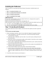
COM controlled devices may include devices such as PTZ, joystick/keypad. Connect PTZ cameras to COM 4
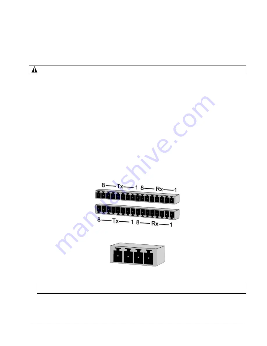
port (Figure 3-5); COM 3 is an optional port used to connect PTZ cameras using a V1400X-IDL (Figure 3-6A).
Refer to AA112-05-0X for a PTZ Connection Guide and AA112-09-0X for PTZ Joystick/Keypad Connection
Guide.
To connect a COM controlled device to the Kollector Force:
1. Using a twisted-pair cable as defined in
Chapter 9, Twisted-Pair Cable Recommendations
, prepare a
4-conductor plus shield type cable by stripping the ends back for use.
2. Connect the COM controlled device to the terminal block connector (while it is disconnected from the
Kollector).
3. Connect the terminal block connector to the RS422/RS485 TX/RX connectors on the rear panel.
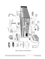
Figure 3-5: Connecting the Terminal Block Connectors on Kollector Force
TX- TX+ RX- RX+
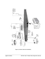
Figure 3-6A: Kollector Force COM 3 Port
NOTE: Ensure that the wires are connected in the correct positions and to the correct polarity (either TX+
and TX- or RX+ and RX-), depending on the type of the device.
4. Install the other end of this cable into the COM controlled device to communicate with the Kollector.
16
•
Installation
XX112-06-01 Rev 911 Kollector Network Digital Video Recorders