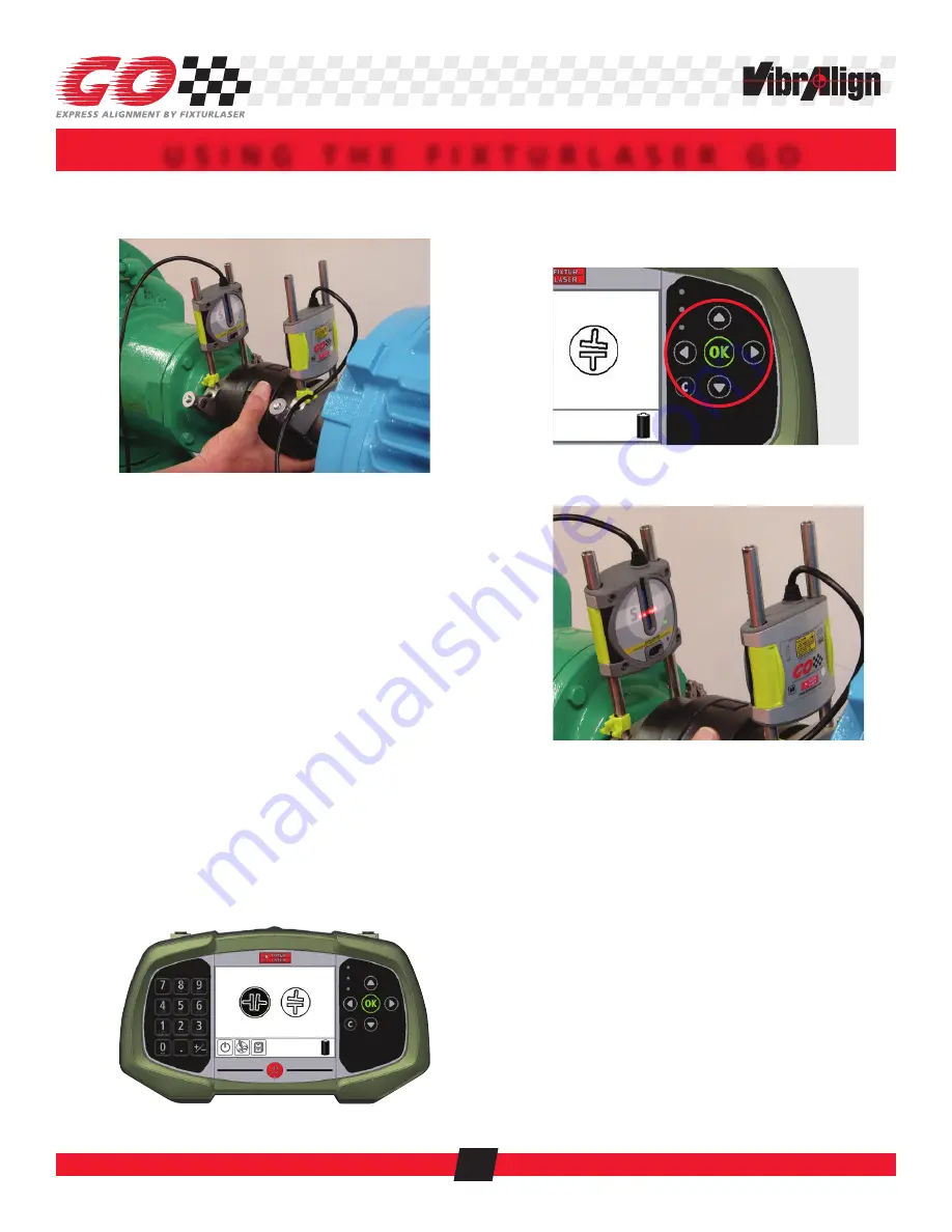
1. SET UP THE FIXTURLASER GO
1.1 Mount the “S” sensor on the stationary shaft.
The sensors may be mounted on the shafts or on
the coupling hubs.
Place the bracket on the shaft and pull the chain
under the shaft and hook it over the pin.
Hand tighten the nut, then ½ turn more with the
wrench.
1.2 Mount the “M” sensor on the movable shaft.
Place the bracket on the shaft and pull the chain
under the shaft and hook it over the pin.
Hand tighten the nut.
Visually align the sensors (side to side), then
tighten the nut ½ turn more with the wrench.
1.3 Connect the cables into either connector on the
display unit.
1.4 Turn the unit on by pressing the RED button at the
center bottom of the display.
1.5 The Horizontal Shaft Alignment coupling icon will
be highlighted in black. Press the “OK” button on
the right hand key pad to enter the Horizontal Shaft
Alignment program.
Use the up/down & left/right arrow buttons
on the right hand key pad to move the black
highlight to the different icons as needed. Press
the “OK” button to select.
1.6 Rotate the sensors to 12:00.
1.7 Aim the lasers.
The sensors will be on different elevations.
Open the green latches on either sensor and
slide up or down to aim the laser into the light
grey band on the opposite sensor. Adjusting one
sensor will adjust both.
You should see both “S” and “M” values in the
boxes at the top of the display.
If you do not, then the lasers are not within the
sensors.
Lock the green latches.
2. ENTER DIMENSIONS
2.1 Measure the distance between the “S” and “M”
sensors to the nearest
1
⁄
8
".
U S I N G T H E F I X T U R L A S E R G O
7


