


Vertiv
|
NetSure™ 2100 Series -48 VDC Power System Installation Manual (IM582138000)
|
Rev. C
48
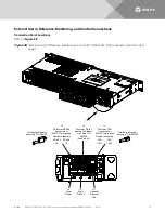
Temperature Probe Port Connectors J8 and J9
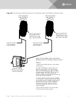
Temp Probe Port 1 connector (J9) and Temp Probe Port 2 connector (J8) are used to connect temperature
probes to the system. See
NOTE!
Each temperature probe consists of two or three pieces that plug together to make a complete
probe. See SAG582138000 for part numbers and descriptions.
Any combination of the temperature probes can be programmed to monitor ambient temperature and/or
battery temperature. A temperature probe set to monitor battery temperature can also be used for the rectifier
battery charge temperature compensation feature, or the battery charge temperature compensation feature
can be programmed to use the average or highest value of all battery temperature probes. The battery charge
temperature compensation feature allows the controller to automatically increase or decrease the output
voltage of the system to maintain battery float current as battery temperature decreases or increases,
respectively. Battery life can be extended when an optimum charge voltage to the battery with respect to
temperature is maintained. A temperature probe set to monitor battery temperature can also be used for the
BTRM (Battery Thermal Runaway Management) feature. The BTRM feature lowers output voltage when a high
temperature condition exists to control against battery thermal runaway.
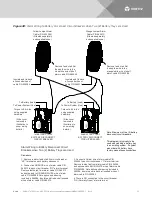
The temperature sensor end of the probe contains a tab with a 5/16” clearance hole for mounting.
A temperature probe programmed to monitor battery temperature should be mounted on the negative post of
a battery cell to sense battery temperature. A temperature probe used for battery charge temperature
compensation and/or BTRM (Battery Thermal Runaway Management) should also be mounted on the negative
post of a battery cell. A temperature probe programmed to monitor ambient temperature should be mounted
in a convenient location, away from direct sources of heat or cold.
Procedure
1.
Connect up to two (2) temperature probes to the system using Temp Probe Port 1 connector (J9) and
Temp Probe Port 2 connector (J8). See
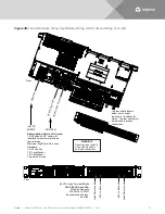
Optional External IB4 Connector J11
The external IB4 connector (J11) is used to connect the Optional External IB4 Kit P/N 559239 to the system.
See
Procedure
1.
Refer to “Installing an Optional External IB4 Kit P/N 559239” on page 38 for a procedure.
Digital Inputs and Relay Outputs Connector J3
Digital inputs and relay outputs connector J3 is used to connect external digital inputs into the system and to
connect relay outputs from the system to external alarm/control circuits. See
NOTE!
Digital input and relay output cable P/N 565286 is available (see SAG582138000). One end
connects to connector J3 located on the rear of the shelf. The other end has unterminated leads for
connections into customer circuits. Refer to


