


Vertiv
|
NetSure™ 2100 Series -48 VDC Power System Installation Manual (IM582138000)
|
Rev. C
40
MAKING ELECTRICAL CONNECTIONS
Important Safety Instructions
DANGER!
Adhere to the “Important Safety Instructions” starting on page 7.
Wiring Considerations
All wiring and branch circuit protection should follow the current edition of the American National Standards
Institute (ANSI) approved National Fire Protection Association's (NFPA) National Electrical Code (NEC), and
applicable local codes. For operation in countries where the NEC is not recognized, follow applicable codes.
For wire size, branch circuit protection, crimp lug, and general wiring recommendations; refer to System
Application Guide SAG582138000. Lugs must be crimped per lug manufacturer’s specifications.
Relay Rack / Cabinet Frame Grounding Connection
For relay rack / cabinet frame grounding requirements, refer to the current edition of the American National
Standards Institute (ANSI) approved National Fire Protection Association's (NFPA) National Electrical Code
(NEC), applicable local codes, and your specific site requirements.
Procedure
1.
Attach a customer grounding network lead to the equipment mounting rack per site requirements.
Holes are provided on the top of each relay rack for installing a lead with a two-hole lug that has 1/4" bolt
clearance holes on 5/8" centers. When using 1/4-inch hardware, recommended torque is 84 in-lbs when
a standard flat washer and lock washer are used. Refer to
NOTE!
REMOVE TAPE FROM HOLE LOCATIONS BEFORE INSTALLING LUG.
NOTE!
The DC return connection to this system can remain isolated from system frame and chassis
(DC-I).
NOTE!
This system is suitable for installation as part of the Common Bonding Network (CBN).
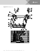
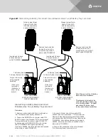
Figure 24:
Relay Rack Frame Grounding Connection Points
Frame Ground
Connection Point
(1/4” clearance holes on 5/8” centers)
Frame Ground
Connection Point
(1/4” clearance holes on 5/8” centers)
Top View
(Typical Relay Rack)
Top View
(Typical Relay Rack)


