


Vertiv
|
NetSure™ 2100 Series -48 VDC Power System Installation Manual (IM582138000)
|
Rev. C
46
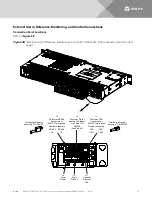
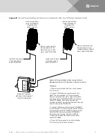
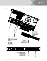
External Alarm, Reference, Monitoring, and Control Connection Point Locations (cont’d from
previous page)
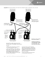
DETAIL A
J3
Customer Digital
Inputs and Outputs
Via Cable P/N
565286
The controller relay assigned to
“Critical Summary” alarm (relay 1 by
default) will operate in the “Fail Safe
Mode”. “Fail Safe Mode” means
Relay 1 is de-energized during an
alarm condition, opening the
contacts between the C and NO
terminals, and closing the contacts
between the C and NC terminals.
The controller’s remaining three (3)
relays energize during an alarm
condition, closing the contacts
between the C and NO terminals,
and opening the contacts between
the C and NC terminals.
J3 Pin-Outs and
Customer Digital Inputs and Outputs
Cable P/N 565286 Color Scheme
Pin 1
DI 1+
W-BL
Pin 3
DI 1-
W-O
Pin 5
DO 2_NC
W-G
Pin 7
DO 2_COM
W-BR
Pin 9
DO 2_NO
W-S
Pin 11
DO 4_NC
R-BL
Pin 13
DO 4_COM
R-O
Pin 15
DO 4_NO
R-G
Pin 2
DI 2+
BL-W
Pin 4
DI 2-
O-W
Pin 6
DO 1_NC
G-W
Pin 8
DO 1_COM
BR-W
Pin 10
DO 1_NO
S-W
Pin 12
DO 3_NC
BL-R
Pin 14
DO 3_COM
O-R
Pin 16
DO 3_NO
G-R


